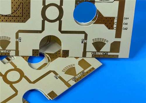
Rogers CLTE-MW 2-Layer 0.15mm Immersion Gold PCB – Microwave & Satellite Communication1. Introduction to Rogers CLTE-MW PCB CLTE-MW laminates provide PCB designers a high performance, cost-effective material, well suited for applications with thickness limitations due to physical or electrical constraints. This unique laminate system is available in seven thickness options, from 3 to 10 mils, ensuring that ideal signal to ground spacing exists for 5G and other millimeter wave applications. The CLTE-MW laminates are reinforced with spread glass which, along with a high filler loading, helps minimize the high frequency glass weave effects on electromagnetic wave propagation. CLTE-MW laminates are ceramic filled, woven glass reinforced PTFE composites. The woven glass reinforcement provides excellent dimensional stability. Other key features include low z-axis CTE for excellent plated through hole reliability, a low loss tangent to enable low loss designs, and low moisture absorption to ensure stable performance in a range of operating environments. This 2-layer rigid PCB is constructed entirely with Rogers CLTE-MW as the core material, making it ideal for demanding microwave, aerospace, and satellite communication applications.
2. Key Features of Rogers CLTE-MW PCB Low loss tangent of 0.0015 at 10 GHz Low Z-axis CTE of 30 ppm/°C Thermal conductivity of 0.42 W/(m·K) UL 94 V-0 flammability rating Low moisture absorption of 0.03% High dielectric strength of 630 V/mil Available in seven thickness options from 3 to 10 mils Spread glass reinforcement minimizes glass weave effects 3. Benefits of Rogers CLTE-MW PCB Enables low loss designs Excellent plated through hole (PTH) reliability Good heat dissipation in aggressive designs Compatible with commercial applications Reliable mechanical performance under thermally challenging environments Excellent dimensional stability Stable performance in a range of operating environments 4. Rogers CLTE-MW PCB Construction Details
5. PCB Stackup (2-Layer Rigid Structure) Copper_layer_1 - 35 μm CLTE-MW Core - 0.076 mm (2.99 mil) Copper_layer_2 - 35 μm 6. PCB Statistics Components: 19 Total Pads: 36 Thru Hole Pads: 21 Top SMT Pads: 15 Bottom SMT Pads: 0 Vias: 12 Nets: 4 7. Primary Application Areas Commercial communications and avionics Military / aerospace applications Microwave feed networks Phase sensitive electronic structures Satellite communication systems Passive components (couplers, filters & baluns) Amplifiers and antennas 8.Quality Assurance Type of artwork supplied: Gerber RS-274-X 9. Rogers CLTE-MW Low-Loss Ceramic-Filled PTFE – Product Introduction CLTE-MW laminates are ceramic filled, woven glass reinforced PTFE composites. CLTE-MW laminates were developed to provide a cost effective, high performance material for the circuit designer. This unique laminate system is well suited for applications that have limitations in thickness due to either physical or electrical constraints. The seven available thickness options from 3 mils to 10 mils ensure that ideal signal to ground spacing exists for today's 5G and other millimeter wave designs. In addition, a variety of copper foil options are available including rolled, reverse treated ED, and standard ED. Resistive foil and metal plate options are also available upon request. The CLTE-MW laminates are reinforced with spread glass, which along with a high filler loading helps minimize the high frequency glass weave effects on electromagnetic wave propagation. The woven glass reinforcement also provides excellent dimensional stability. Other key features of the laminate include low z-axis CTE (30 ppm/°C) for excellent plated through hole reliability, a low loss tangent of 0.0015 at 10 GHz to enable low loss designs, and low moisture absorption of 0.03% to ensure stable performance in a range of operating environments. Thermal conductivity of 0.42 W/(m·K) enables heat dissipation in aggressive designs along with a high dielectric strength of 630 V/mil to ensure good z-axis insulation between conductor layers. The UL 94 V-0 flammability rating enables the use of CLTE-MW laminates in commercial applications. CLTE-MW laminates are well suited for a range of applications including amplifiers, antennas, baluns, couplers and filters. Applicable markets range from commercial and consumer to defense and aerospace.
10. Features and Benefits Summary
11.Rogers CLTE-MW Data Sheet
12.CLTE-MW Dielectric Constant by Thickness
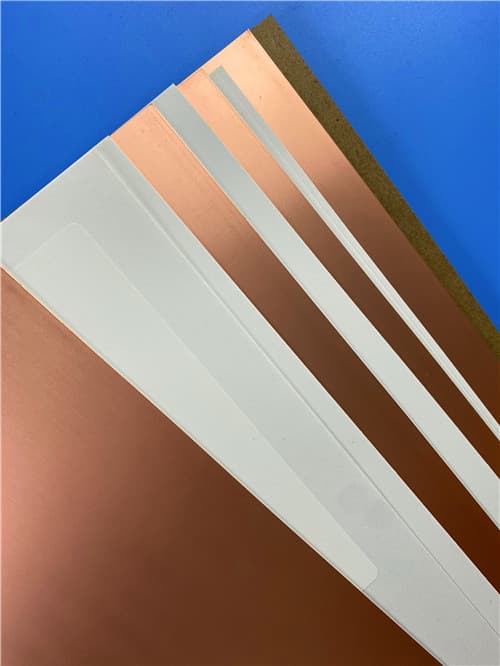
13.Some Typical Applications Commercial communications and avionics Military / aerospace applications Microwave feed networks Phase sensitive electronic structures Satellite communication systems Passive components (couplers, filters & baluns) Amplifiers and antennas 14.Standard Thicknesses, Panel Sizes & Claddings Standard Thicknesses 0.003" (0.076 mm) ± 0.0005" 0.004" (0.102 mm) ± 0.0005" 0.005" (0.127 mm) ± 0.0007" 0.006" (0.152 mm) ± 0.0007" 0.007" (0.178 mm) ± 0.0010" 0.008" (0.203 mm) ± 0.0010" 0.010" (0.254 mm) ± 0.0010" Standard Panel Sizes 12" x 18" (305 x 457 mm) 24" x 18" (610 x 457 mm) Standard Claddings Reverse Treated Electrodeposited Copper Foil: 1/2 oz (18 μm), 1 oz (35 μm), 2 oz (70 μm) Very Low Profile Electrodeposited Copper Foil: 1/4 oz (9 μm), 1/2 oz (18 μm), 1 oz (35 μm) |
Get a Quick Quote
Fill in the form below and our engineers will reply within 24 hours with technical specifications and pricing for Rogers CLTE-MW 2-Layer 0.15mm Immersion Gold PCB.