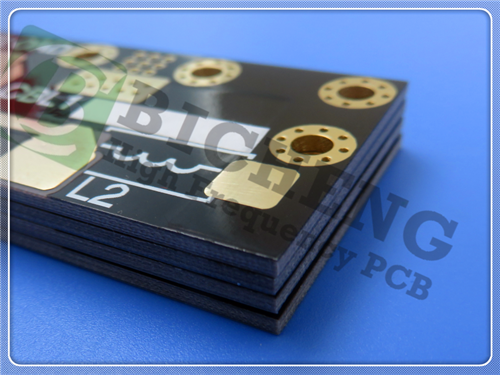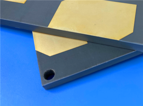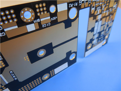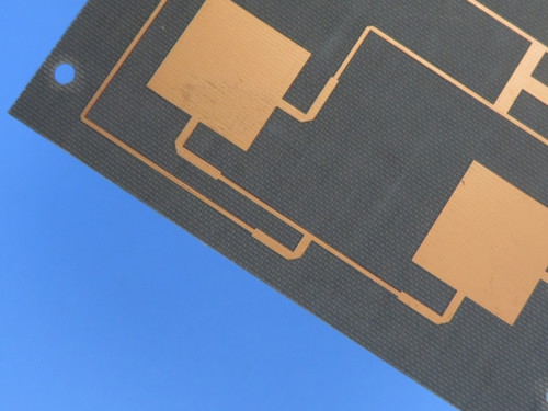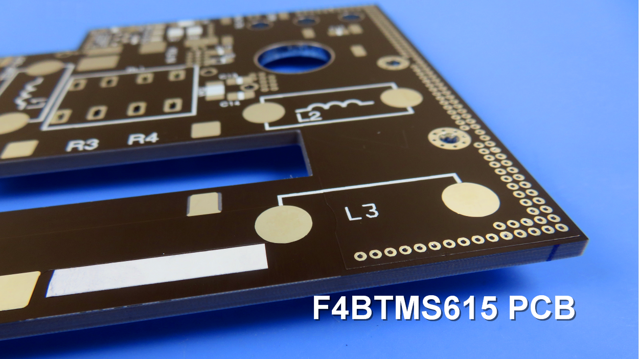
Wangling F4BTMS1000 2-Layer 0.4mm OSP PCB – Aerospace & RF Applications1. Introduction to Wangling F4BTMS1000 PCB The F4BTMS series is an upgraded version of the F4BTM series. It has achieved a technological breakthrough in material formulation and manufacturing processes. The material has been enriched with a significant amount of ceramics and reinforced with ultra-thin and ultra-fine glass fiber cloth, resulting in substantial improvements in material performance and a broader range of dielectric constants. It is a high-reliability material suitable for aerospace applications and can replace similar foreign products. By incorporating a small amount of ultra-thin and ultra-fine glass fiber cloth and a large amount of uniformly distributed special nano-ceramics mixed with polytetrafluoroethylene resin, the negative effects of glass fiber on electromagnetic wave propagation are minimized. This reduces dielectric loss, enhances dimensional stability, and decreases the X/Y/Z anisotropy of the material. It also increases the usable frequency range, improves electrical strength, and enhances thermal conductivity. Additionally, the material exhibits excellent low thermal expansion coefficient and stable dielectric temperature characteristics. The F4BTMS series comes with RTF low roughness copper foil as a standard feature, which reduces conductor loss and provides excellent peel strength. It can be used with either copper or aluminum bases. This 2-layer rigid PCB is constructed entirely with Wangling F4BTMS1000 as the core material, making it ideal for demanding aerospace, military radar, satellite communication, and phase-sensitive antenna applications.
2. Key Features of Wangling F4BTMS1000 PCB Dielectric constant (Dk) of 10.2 at 10 GHz with tolerance of ±0.2 Dissipation factor of 0.0020 at 10 GHz and 0.0023 at 20 GHz CTE X-axis: 16 ppm/°C, Y-axis: 18 ppm/°C, Z-axis: 32 ppm/°C (-55°C to 288°C) Low thermal coefficient of Dk: -320 ppm/°C (-55°C to 150°C) High thermal conductivity of 0.81 W/(m·K) Low moisture absorption of 0.03% UL 94 V-0 flammability rating Excellent radiation resistance and low outgassing performance Stable Dk and low loss up to 40 GHz 3. Benefits of Wangling F4BTMS1000 PCB Tight Dk tolerance and excellent batch-to-batch consistency Ultra-low dielectric loss Stable Dk and low loss up to 40 GHz for phase-sensitive applications Excellent temperature coefficient of Dk and loss for phase stability from -55°C to 150°C Excellent radiation resistance after dose irradiation Low outgassing performance meeting aerospace vacuum requirements Low X/Y/Z CTE for dimensional thermal stability and PTH reliability High thermal conductivity for higher power applications Excellent dimensional stability Low moisture absorption Standard RTF low roughness copper foil reduces conductor loss and provides excellent peel strength Compatible with standard PTFE board processing techniques, suitable for multilayer and high-density hole processing 4.Wangling F4BTMS1000 PCB Construction Details
5. PCB Stackup (2-Layer Rigid Structure) Copper_layer_1 - 35 μm (1 oz) F4BTMS1000 Core - 0.254 mm (10 mil) Copper_layer_2 - 35 μm (1 oz) 6. PCB Statistics Components: 42 Total Pads: 78 Thru Hole Pads: 41 Top SMT Pads: 37 Bottom SMT Pads: 0 Vias: 36 Nets: 2 7. Primary Application Areas Aerospace equipment, space and cabin equipment Microwave and RF Radar and military radar Feed networks Phase-sensitive antennas and phased array antennas Satellite communications and more 8.Quality Assurance Type of artwork supplied: Gerber RS-274-X 9. Wangling F4BTMS1000 Ceramic-Filled PTFE Laminate – Product Introduction The F4BTMS series is an upgraded version of the F4BTM series. It has achieved a technological breakthrough in material formulation and manufacturing processes. The material has been enriched with a significant amount of ceramics and reinforced with ultra-thin and ultra-fine glass fiber cloth, resulting in substantial improvements in material performance and a broader range of dielectric constants. It is a high-reliability material suitable for aerospace applications and can replace similar foreign products. By incorporating a small amount of ultra-thin and ultra-fine glass fiber cloth and a large amount of uniformly distributed special nano-ceramics mixed with polytetrafluoroethylene resin, the negative effects of glass fiber on electromagnetic wave propagation are minimized. This reduces dielectric loss, enhances dimensional stability, and decreases the X/Y/Z anisotropy of the material. It also increases the usable frequency range, improves electrical strength, and enhances thermal conductivity. Additionally, the material exhibits excellent low thermal expansion coefficient and stable dielectric temperature characteristics. The F4BTMS series comes with RTF low roughness copper foil as a standard feature, which reduces conductor loss and provides excellent peel strength. It can be used with either copper or aluminum bases. The material can be processed using standard PTFE board processing techniques. Its excellent mechanical and physical properties make it suitable for multilayer, high-multilayer, and backplane processing, while also demonstrating excellent machinability for dense hole and fine line processing.
10. Features and Benefits Summary
11. Wangling F4BTMS1000 Data Sheet
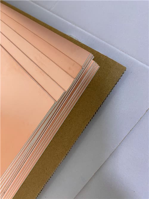
12. Some Typical Applications Aerospace equipment, space and cabin equipment Microwave and RF Radar and military radar Feed networks Phase-sensitive antennas and phased array antennas Satellite communications and more 13. Standard Thicknesses, Panel Sizes & Claddings Standard Dielectric Thicknesses (F4BTMS1000 minimum 0.254mm, available in 0.127mm multiples)
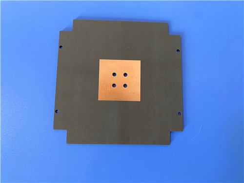
Available Copper Foils Copper thickness: 0.5 oz (0.018 mm), 1 oz (0.035 mm); other thicknesses available by custom order Copper foil type: RTF low roughness copper foil (standard) Optional: 50Ω embedded resistor copper foil (nickel-phosphorus alloy, 0.2μm thickness, 50±5Ω per square cm), aluminum base, copper base Standard Panel Sizes 305 x 460 mm (12" x 18") 460 x 610 mm (18" x 24") 610 x 920 mm (24" x 36") Metal-Backed Options (Aluminum or Copper Base) Models: F4BTMS1000-AL (aluminum base), F4BTMS1000-CU (copper base)
|
Get a Quick Quote
Fill in the form below and our engineers will reply within 24 hours with technical specifications and pricing for Wangling F4BTMS1000 2-Layer 0.4mm OSP PCB.
.jpg)
.jpg)