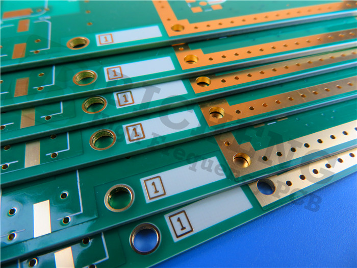
Rogers High Frequency PCB Built on RO4730G3 60mil 1.524mm DK3.0 with Immersion Gold for Cellular Base Station Antennas
(Printed Circuit Boards are custom-made products; the pictures and parameters shown are for reference only.)
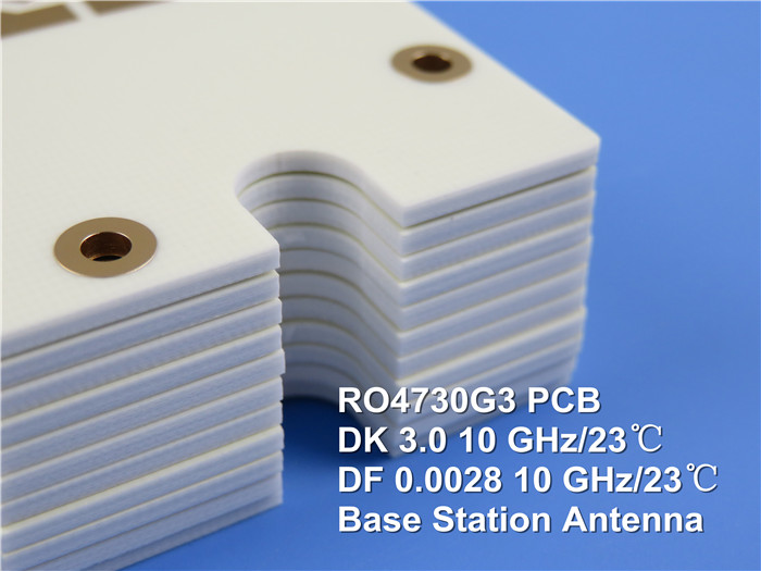
Rogers RO4730G3 antenna-grade laminates provide a reliable and cost-effective alternative to conventional PTFE-based laminates. These materials possess the essential mechanical and electrical properties that antenna designers require. With a dielectric constant of 3.0 and a loss tangent of 0.0022 measured at 2.5 GHz using LoPro Reverse Treated EDC foil, these laminates enable designers to achieve substantial gain while minimizing signal loss. Additionally, they demonstrate low Passive Intermodulation (PIM) performance, with values exceeding -160 dBc.
RO4730G3 materials are compatible with standard epoxy and high-temperature lead-free solder processes. Unlike traditional PTFE-based laminates, they do not require special treatments for plated through hole preparation. Multi-layer configurations can be achieved using RO4450F bondply at 175 ℃. The resin systems of RO4730G3 are specifically designed to meet the needs of antenna designers, boasting a glass transition temperature that exceeds 280°C. This leads to a low Z-axis Coefficient of Thermal Expansion (CTE), excellent reliability for plated through holes, and superior lead-free solder processability.
Typical application is cellular base station antennas.
General Description
This is a double-sided RF PCB constructed from 1.524mm (60mil) RO4730G3, specifically designed for Cellular Base Station Antenna applications.
Basic Specifications
| Basic Specifications | Description |
|---|---|
| Base Material | RO4730G3 60mil (1.524mm) |
| Dielectric Constant | 3.0 ± 0.05 |
| Layer Count | 2 layers |
| Type | Through holes |
| Format | 110mm x 95mm = 1 type = 1 piece |
| Surface Finish | Immersion gold |
| Copper Weight | Outer layer 35 μm |
| **Solder Mask | Legend** |
| Final PCB Height | 1.6 mm |
| Standard | IPC 6012 Class 2 |
| Packing | 20 pieces per shipment |
| Lead Time | 7 working days |
| Shelf Life | 6 months |
(Data Sheet of Rogers 4730 (RO4730G3))
RO4730G3 Typical Value |
|||||
Property |
RO4730G3 |
Direction |
Units |
Condition |
Test Method |
Dielectric Constant,εProcess |
3.0±0.5 |
Z |
|
10 GHz 23℃ |
IPC-TM-650 2.5.5.5 |
Dielectric Constant,εDesign |
2.98 |
Z |
|
1.7 GHz to 5 GHz |
Differential Phase Length Method |
Dissipation Factor,tanδ |
0.0028 |
Z |
|
10 GHz 23℃ |
IPC-TM-650 2.5.5.5 |
|
2.5 GHz |
||||
Thermal Coefficient of ε |
+34 |
Z |
ppm/℃ |
-50 ℃to 150℃ |
IPC-TM-650 2.5.5.5 |
Dimensional Stability |
<0.4 |
X, Y |
mm/m |
after etech +E2/150 ℃ |
IPC-TM-650 2.4.39A |
Volume Resistivity (0.030") |
9 X 10⁷ |
|
MΩ.cm |
COND A |
IPC-TM-650 2.5.17.1 |
Surface Resistivity (0.030") |
7.2 X 10⁵ |
|
MΩ |
COND A |
IPC-TM-650 2.5.17.1 |
PIM |
-165 |
|
dBc |
50 ohm 0.060" |
43 dBm 1900 MHz |
Electrical Strength (0.030") |
730 |
Z |
V/mil |
|
IPC-TM-650 2.5.6.2 |
Flexural Strength MD |
181 (26.3) |
|
Mpa (kpsi) |
RT |
ASTM D790 |
CMD |
139 (20.2) |
|
|||
Moisure Absorption |
0.093 |
- |
% |
48/50 |
IPC-TM-650 2.6.2.1 ASTM D570 |
Thermal Conductivity |
0.45 |
Z |
W/mK |
50℃ |
ASTM D5470 |
Coefficient of Thermal Expansion |
15.9 |
X |
ppm/℃ |
-50 ℃to 288℃ |
IPC-TM-650 2.4.4.1 |
Tg |
>280 |
|
℃ |
|
IPC-TM-650 2.4.24 |
Td |
411 |
|
℃ |
|
ASTM D3850 |
Density |
1.58 |
|
gm/cm3 |
|
ASTM D792 |
Copper Peel Stength |
4.1 |
|
pli |
1oz,LoPro EDC |
IPC-TM-650 2.4.8 |
Flammability |
V-0 |
|
|
|
UL 94 |
Lead-free Process Compatible |
Yes |
|
|
|
|