Rogers TMM10 High Frequency PCB - Complete Technical Guide
 August 9,2025
Introduction
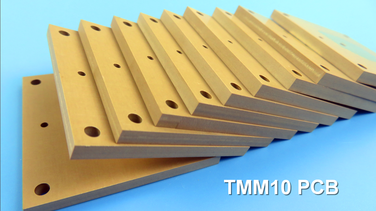
Rogers TMM10 is a premium ceramic-thermoset composite material engineered for high-reliability stripline and microstrip applications. Combining the benefits of PTFE and ceramic substrates without their limitations, TMM10 delivers exceptional electrical and mechanical performance for demanding RF designs.
Key Features
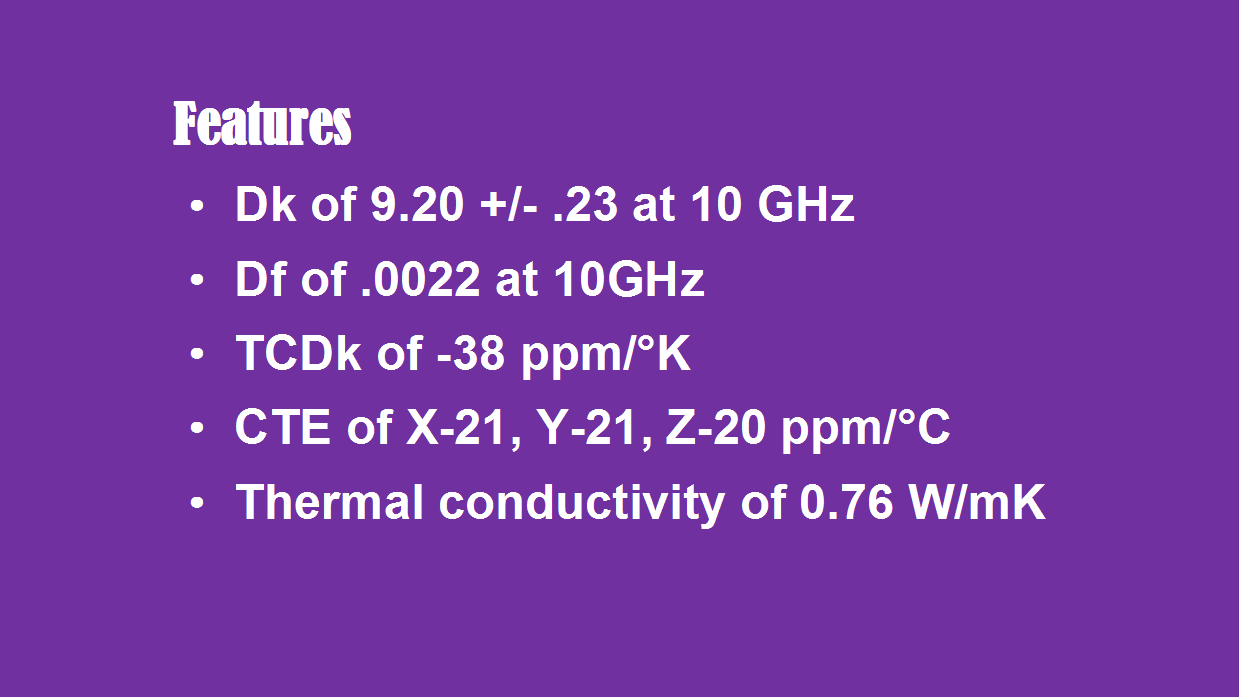
High Dielectric Constant (Dk): 9.20 ± 0.23 (enables circuit miniaturization)
Ultra-Low Loss: Dissipation factor of 0.0022 @ 10GHz
Temperature Stability: -38 ppm/°K thermal coefficient of Dk
Matched CTE: 21 ppm/°K (X/Y), 20 ppm/°K (Z) for reliable PTH connections
Enhanced Thermal Conductivity: 0.76 W/mK (2× better than standard PTFE)
Mechanical Durability: Excellent resistance to creep and cold flow
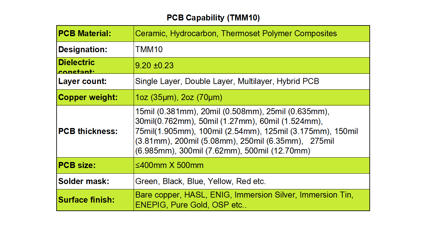
PCB Manufacturing Capabilities
Layer Options: Single, double, multi-layer & hybrid configurations
Copper Weights: 1oz (35µm) & 2oz (70µm)
Thickness Range: 15mil (0.38mm) to 500mil (12.7mm)
Max Board Size: 400mm × 500mm
Surface Finishes: ENIG, HASL, Immersion Silver/Tin, ENEPIG, OSP, Pure Gold
Solder Mask Colors: Green, black, blue, yellow, red
Applications
Satellite communication systems
GPS and patch antennas
Dielectric polarizers
High-frequency chip testers
Military/aerospace RF components