F4BTM High Frequency PCB: Advanced Laminates for Superior Performance
(PCB's are custom-made products, the picture and parameters shown are just for reference)
Introduction
The F4BTM High Frequency PCB series features advanced laminates crafted from a scientifically formulated blend of fiberglass cloth, nano-ceramic fillers, and polytetrafluoroethylene (PTFE) resin. These materials undergo stringent pressing processes to create a reliable product. Built upon the F4BM dielectric layer, the addition of high-dielectric, low-loss nano-level ceramics results in a laminate with a higher dielectric constant, improved thermal resistance, a lower thermal expansion coefficient, enhanced insulation resistance, and superior thermal conductivity, all while maintaining low loss characteristics.
The F4BTM and F4BTME laminates utilize the same dielectric layer but differ in their copper foil applications: F4BTM is combined with ED copper foil for applications that do not require Passive Intermodulation (PIM) performance, while F4BTME uses reverse-treated (RTF) copper foil, providing excellent PIM characteristics, precise line control, and reduced conductor loss.
Features & Benefits
1.Dielectric Constant (DK): Available in a range from 2.98 to 3.5.
2.Performance Enhancement: The incorporation of ceramics significantly boosts laminate performance.
3.PIM Excellence: F4BTME demonstrates outstanding passive intermodulation performance.
4.Variety and Cost Efficiency: Available in various thicknesses and sizes, offering cost-effective solutions for PCB manufacturing.
5.Commercial Viability: Suitable for large-scale production, ensuring high cost-effectiveness in PCB applications.
6.Durability: Features radiation resistance and low outgassing properties for reliability in demanding PCB environments.
Models & Data Sheet
| Product Technical Parameters | Product Models & Data Sheet | ||||||
| Product Features | Test Conditions | Unit | F4BTM298 | F4BTM300 | F4BTM320 | F4BTM350 | |
| Dielectric Constant (Typical) | 10GHz | / | 2.98 | 3.0 | 3.2 | 3.5 | |
| Dielectric Constant Tolerance | / | / | ±0.06 | ±0.06 | ±0.06 | ±0.07 | |
| Loss Tangent (Typical) | 10GHz | / | 0.0018 | 0.0018 | 0.0020 | 0.0025 | |
| 20GHz | / | 0.0023 | 0.0023 | 0.0026 | 0.0035 | ||
| Dielectric Constant Temperature Coefficient | -55 º~150ºC | PPM/℃ | -78 | -75 | -75 | -60 | |
| Peel Strength | 1 OZ F4BTM | N/mm | >1.6 | >1.6 | >1.6 | >1.6 | |
| 1 OZ F4BTME | N/mm | >1.4 | >1.4 | >1.4 | >1.4 | ||
| Volume Resistivity | Standard Condition | MΩ.cm | ≥1×10^7 | ≥1×10^7 | ≥1×10^7 | ≥1×10^7 | |
| Surface Resistivity | Standard Condition | MΩ | ≥1×10^6 | ≥1×10^6 | ≥1×10^6 | ≥1×10^6 | |
| Electrical Strength (Z direction) | 5KW,500V/s | KV/mm | >26 | >30 | >32 | >32 | |
| Breakdown Voltage (XY direction) | 5KW,500V/s | KV | >34 | >35 | >40 | >40 | |
| Coefficientof Thermal Expansion | XY direction | -55 º~288ºC | ppm/ºC | 15,16 | 15,16 | 13,15 | 10,12 |
| Z direction | -55 º~288ºC | ppm/ºC | 78 | 72 | 58 | 51 | |
| Thermal Stress | 260℃, 10s,3 times | No delamination | No delamination | No delamination | No delamination | ||
| Water Absorption | 20±2℃, 24 hours | % | ≤0.05 | ≤0.05 | ≤0.05 | ≤0.05 | |
| Density | Room Temperature | g/cm3 | 2.25 | 2.25 | 2.20 | 2.20 | |
| Long-Term Operating Temperature | High-Low Temperature Chamber | ℃ | -55~+260 | -55~+260 | -55~+260 | -55~+260 | |
| Thermal Conductivity | Z direction | W/(M.K) | 0.42 | 0.42 | 0.50 | 0.54 | |
| PIM | Only applicable to F4BTME | dBc | ≤-160 | ≤-160 | ≤-160 | ≤-160 | |
| Flammability | / | UL-94 | V-0 | V-0 | V-0 | V-0 | |
| Material Composition | / | / | PTFE, Fiberglass Cloth, nano-ceramics F4BTM paired with ED copper foil, F4BTME paired with reverse-treated (RTF) copper foil. |
||||
Our PCB Capability (F4BTM)
| PCB Capability (F4BTM) | |||
| PCB Material: | PTFE / glass fiber cloth / Nano-ceramic filler | ||
| Designation (F4BTM ) | F4BTM | DK (10GHz) | DF (10 GHz) |
| F4BTM298 | 2.98±0.06 | 0.0018 | |
| F4BTM300 | 3.0±0.06 | 0.0018 | |
| F4BTM320 | 3.2±0.06 | 0.0020 | |
| F4BTM350 | 3.5±0.07 | 0.0025 | |
| Layer count: | Single Sided, Double Sided PCB, Multilayer PCB, Hybrid PCB | ||
| Copper weight: | 0.5oz (17 µm), 1oz (35µm), 2oz (70µm) | ||
| Dielectric thickness (or overall thickness) | 0.25mm, 0.508mm, 0.762mm, 0.8mm, 1.0mm, 1.016mm, 1.27mm, 1.524mm, 2.0mm, 3.0mm, 4.0mm, 5.0mm, 6.0mm, 8.0mm, 10.0mm, 12.0mm | ||
| PCB size: | ≤400mm X 500mm | ||
| Solder mask: | Green, Black, Blue, Yellow, Red etc. | ||
| Surface finish: | Bare copper, HASL, ENIG, Immersion silver, Immersion tin, OSP, Pure gold, ENEPIG etc.. | ||
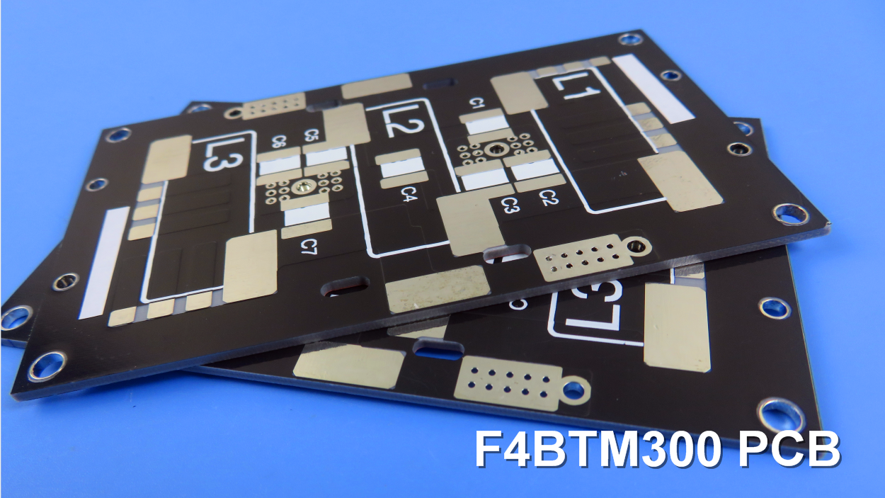
F4BTM PCB and Applications
An example of a DK 3.0 F4BTM PCB is displayed, constructed on a 1.524mm substrate featuring HASL surface finishes.
This PCB type is utilized in a wide range of applications, including:
Antennas
Mobile Internet
Sensor Networks
Radar Systems
Millimeter Wave Radar
Aerospace Technologies
Satellite Navigation
Beidou Systems
Missile Guidance
Power Amplifiers
Radio Frequency Applications
Final Note on F4BTM Substrates
The F4BTM series can be offered in aluminum-based or copper-based materials, where one side of the dielectric layer is covered with copper foil, and the other side is covered with either aluminum or copper materials. This configuration aids in shielding and heat dissipation.
For example, F4BTM300-AL denotes the F4BTM300 model with an aluminum-based substrate.