F4BTMS High Frequency PCB for Superior Performance
(PCB's are custom-made products, the picture and parameters shown are just for reference)
Introduction
The F4BTMS series is an upgraded version of the F4BTM series, featuring significant technological advancements in material formulation and manufacturing processes. This series incorporates a high concentration of ceramics and utilizes ultra-thin, ultra-fine fiberglass cloth reinforcement. These enhancements greatly improve performance, resulting in a wider range of dielectric constants suitable for high-reliability aerospace applications, effectively replacing similar foreign products.
By integrating ultra-thin fiberglass cloth reinforcement with a uniform mixture of special nanoceramics and polytetrafluoroethylene (PTFE) resin, the F4BTMS series minimizes the fiberglass effect during electromagnetic wave propagation. This reduction decreases dielectric loss and enhances dimensional stability. The material exhibits reduced anisotropy in the X/Y/Z directions, allowing for higher frequency usage, increased electrical strength, and improved thermal conductivity. Additionally, it possesses an excellent low coefficient of thermal expansion and stable dielectric temperature characteristics.
The F4BTMS series features RTF low roughness copper foil, which reduces conductor loss and provides excellent peel strength. It can be paired with either copper-based or aluminum-based options.
For instance, F4BTMS294 can be combined with buried 50Ω resistor copper foil to create a resistor film substrate.
The circuit boards can be processed using standard PTFE fabrication techniques, leveraging the material's excellent mechanical and physical properties. They are suitable for multi-layer, high-layer-count, and backplane processing, and exhibit excellent processability in dense hole and fine line routing.
Product Features
1.Minimal dielectric constant tolerance with excellent batch-to-batch consistency.
2.Extremely low dielectric loss.
3.Stable dielectric constant and low loss at frequencies up to 40GHz, ideal for phase-sensitive applications.
4.Excellent temperature coefficient of dielectric constant and loss, maintaining stability between -55°C and 150°C.
5.Radiation resistance, retaining stable dielectric and physical properties after exposure to irradiation.
6.Low outgassing performance, compliant with vacuum outgassing requirements for aerospace applications.
7.Minimal thermal expansion coefficients in the X/Y/Z directions, ensuring dimensional stability and reliable hole copper connections.
8.Improved thermal conductivity suitable for high-power applications.
9.Excellent dimensional stability.
10.Low water absorption..
Models & Data Sheet
| Product Technical Parameters | Product Models & Data Sheet | ||||||||||||
| Product Features | Test Conditions | Unit | F4BTMS220 | F4BTMS233 | F4BTMS255 | F4BTMS265 | F4BTMS294 | F4BTMS300 | F4BTMS350 | F4BTMS430 | F4BTMS450 | F4BTMS615 | F4BTMS1000 |
| Dielectric Constant (Typical) | 10GHz | / | 2.2 | 2.33 | 2.55 | 2.65 | 2.94 | 3.00 | 3.50 | 4.30 | 4.50 | 6.15 | 10.20 |
| Dielectric Constant Tolerance | / | / | ±0.02 | ±0.03 | ±0.04 | ±0.04 | ±0.04 | ±0.04 | ±0.05 | ±0.09 | ±0.09 | ±0.12 | ±0.2 |
| Dielectric Constant (Design) | 10GHz | / | 2.2 | 2.33 | 2.55 | 2.65 | 2.94 | 3.0 | 3.50 | 4.3 | 4.5 | 6.15 | 10.2 |
| Loss Tangent (Typical) | 10GHz | / | 0.0009 | 0.0010 | 0.0012 | 0.0012 | 0.0012 | 0.0013 | 0.0016 | 0.0015 | 0.0015 | 0.0020 | 0.0020 |
| 20GHz | / | 0.0010 | 0.0011 | 0.0013 | 0.0014 | 0.0014 | 0.0015 | 0.0019 | 0.0019 | 0.0019 | 0.0023 | 0.0023 | |
| 40GHz | / | 0.0013 | 0.0015 | 0.0016 | 0.0018 | 0.0018 | 0.0019 | 0.0024 | 0.0024 | 0.0024 | / | / | |
| Dielectric Constant Temperature Coefficient | -55 º~150ºC | PPM/℃ | -130 | -122 | -92 | -88 | -20 | -20 | -39 | -60 | -58 | -96 | -320 |
| Peel Strength | 1 OZ RTF copper | N/mm | >2.4 | >2.4 | >1.8 | >1.8 | >1.2 | >1.2 | >1.2 | >1.2 | >1.2 | >1.2 | >1.2 |
| Volume Resistivity | Standard Condition | MΩ.cm | ≥1×10^8 | ≥1×10^8 | ≥1×10^8 | ≥1×10^8 | ≥1×10^8 | ≥1×10^8 | ≥1×10^8 | ≥1×10^8 | ≥1×10^8 | ≥1×10^8 | ≥1×10^8 |
| Surface Resistivity | Standard Condition | MΩ | ≥1×10^8 | ≥1×10^8 | ≥1×10^8 | ≥1×10^8 | ≥1×10^8 | ≥1×10^8 | ≥1×10^8 | ≥1×10^8 | ≥1×10^8 | ≥1×10^8 | ≥1×10^8 |
| Electrical Strength (Z direction) | 5KW,500V/s | KV/mm | >26 | >30 | >32 | >34 | >40 | >40 | >42 | >44 | >45 | >48 | >23 |
| Breakdown Voltage (XY direction) | 5KW,500V/s | KV | >35 | >38 | >40 | >42 | >48 | >52 | >55 | >52 | >54 | >55 | >42 |
| Coefficientof Thermal Expansion (X, Y direction) | -55 º~288ºC | ppm/ºC | 40, 50 | 35, 40 | 15, 20 | 15, 20 | 10, 12 | 10, 11 | 10, 12 | 13, 12 | 12, 12 | 10, 12 | 16, 18 |
| Coefficientof Thermal Expansion (Z direction) | -55 º~288ºC | ppm/ºC | 290 | 220 | 80 | 72 | 22 | 22 | 20 | 47 | 45 | 40 | 32 |
| Thermal Stress | 260℃, 10s,3 times | / | No delamination | No delamination | No delamination | No delamination | No delamination | No delamination | No delamination | No delamination | No delamination | No delamination | No delamination |
| Water Absorption | 20±2℃, 24 hours | % | 0.02 | 0.02 | 0.025 | 0.025 | 0.02 | 0.025 | 0.03 | 0.08 | 0.08 | 0.1 | 0.03 |
| Density | Room Temperature | g/cm3 | 2.18 | 2.22 | 2.26 | 2.26 | 2.25 | 2.28 | 2.3 | 2.51 | 2.53 | 2.75 | 3.2 |
| Long-Term Operating Temperature | High-Low Temperature Chamber | ℃ | -55~+260 | -55~+260 | -55~+260 | -55~+260 | -55~+260 | -55~+260 | -55~+260 | -55~+260 | -55~+260 | -55~+260 | -55~+260 |
| Thermal Conductivity | Z direction | W/(M.K) | 0.26 | 0.28 | 0.31 | 0.36 | 0.58 | 0.58 | 0.6 | 0.63 | 0.64 | 0.67 | 0.81 |
| Flammability | / | UL-94 | V-0 | V-0 | V-0 | V-0 | V-0 | V-0 | V-0 | V-0 | V-0 | V-0 | V-0 |
| Material Composition | / | / | PTFE,Ultra-thin and ultra-fine (quartz) fiberglass. | PTFE,Ultra-thin and ultra-fine fiberglass, ceramics. | |||||||||
Our PCB Capability (F4BTMS)
| PCB Capability (F4BTMS) | |||
| PCB Material: | PTFE,Ultra-thin and ultra-fine fiberglass, ceramics. | ||
| Designation (F4BTMS ) | F4BTMS | DK (10GHz) | DF (10 GHz) |
| F4BTMS220 | 2.2±0.02 | 0.0009 | |
| F4BTMS233 | 2.33±0.03 | 0.0010 | |
| F4BTMS255 | 2.55±0.04 | 0.0012 | |
| F4BTMS265 | 2.65±0.04 | 0.0012 | |
| F4BTMS294 | 2.94±0.04 | 0.0012 | |
| F4BTMS300 | 3.0±0.04 | 0.0013 | |
| F4BTMS350 | 3.5±0.05 | 0.0016 | |
| F4BTMS430 | 4.3±0.09 | 0.0015 | |
| F4BTMS450 | 4.5±0.09 | 0.0015 | |
| F4BTMS615 | 6.15±0.12 | 0.0020 | |
| F4BTMS1000 | 10.2±0.2 | 0.0020 | |
| Layer count: | Single Sided, Double Sided PCB, Multilayer PCB, Hybrid PCB | ||
| Copper weight: | 0.5oz (17 µm), 1oz (35µm), 2oz (70µm) | ||
| Dielectric thickness | 0.09mm (3.5mil), 0.127mm (5mil), 0.254mm(10mil),0.508mm(20mil), 0.635mm(25mil), 0.762mm(30mil), 0.787mm(31mil), 1.016mm(40mil), 1.27mm(50mil), 1.5mm(59mil), 1.524mm(60mil), 1.575mm(62mil), 2.03mm(80mil), 2.54mm(100mil), 3.175mm(125mil), 4.6mm(160mil), 5.08mm(200mil), 6.35mm(250mil) | ||
| PCB size: | ≤400mm X 500mm | ||
| Solder mask: | Green, Black, Blue, Yellow, Red etc. | ||
| Surface finish: | Bare copper, HASL, ENIG, Immersion silver, Immersion tin, OSP, Pure gold, ENEPIG etc.. | ||
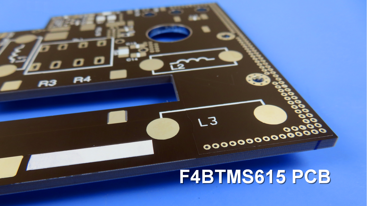
A F4BTMS PCB and Typical Applications:
Presented on the screen is an F4BTMS high-frequency PCB, utilizing a 3.2mm substrate with HASL coating on the pads. F4BTMS PCBs are extensively employed in various domains, including:
Aerospace and aviation equipment, space installations, and cabin setups.
Microwave and RF applications.
Radar systems, particularly in military applications.
Feed networks for signal distribution.
Phase-sensitive antennas and phased array antennas.
Satellite communications, and much more.
Final Note on F4BTM Substrates
The F4BTMS series offers aluminum-based or copper-based materials, where one side of the dielectric layer is covered with copper foil, and the other side is covered with either aluminum or copper materials. This configuration serves to provide shielding or heat dissipation.
For example, F4BTMS220-AL represents the F4BTMS220 model with an aluminum-based substrate, while F4BTMS294-CU denotes the F4BTMS294 model with a copper-based substrate.