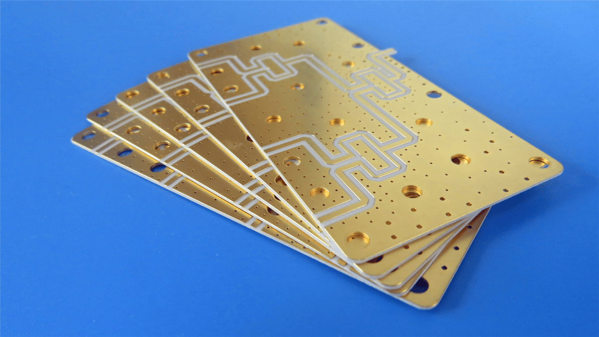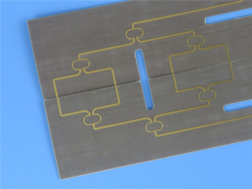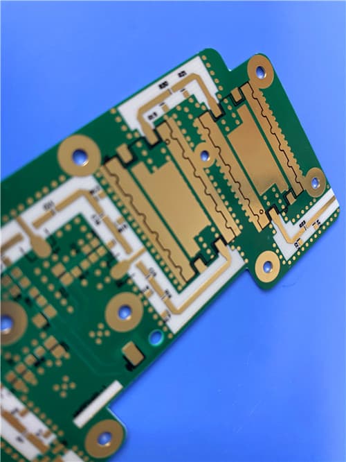
CLTE-AT 2-Layer 5mil Ultra-Thin Ceramic PTFE PCB with Immersion Gold1.Introduction CLTE-A laminates represent the commercial version of the CLTE™ product line.CLTE-AT laminates use the common building blocks developed with CLTE-XT™ laminates, but with some changes to make the product more affordable. This results in a higher dielectric constant (3.00) and a slightly different thickness than the CLTE-XT laminates. CLTE-AT micro dispersed ceramic PTFE composites utilize a woven fiberglass reinforcement to provide the highest degree of dimensional stability, critical in multilayer designs. CLTE-AT laminates are in a “League of their Own” for registration when utilizing thin substrates (i.e. 0.005” and 0.010”). CLTE-AT laminates have “Best-in-Class” Insertion Loss (S21) and Loss Tangent(0.0013) in the commercial marketplace and second only to CLTE-XT laminates. Rogers’ CLTE-AT laminates were designed to provide a quality peel strength without having to resort to the utilization of the lossier, rougher coppers prevalent in competitive products to achieve acceptable copper adhesion. CLTE-AT laminates have Low CTE xyz and Very Low TCEr for applications that require Electrical Phase Stability, Dk Stability, and Mechanical Stability well over a -55 to 150°C Operating Temperature. CLTE-AT laminates continue the competitive advantages of CLTE laminates (dimensional stability, low absorption of moisture and processing chemicals, ease of processability). The higher thermal conductivity of CLTE-AT laminates improve heat transfer relative to alternative materials and enable better power handling. 2.Key Features and Benefits Superior signal integrity Excellent thermal/mechanical performance characteristics Woven glass reinforcement Physical Properties
3.PCB Details
4.PCB Stackup (2-Layer Rigid Structure) 2-layer rigid PCB 5.PCB Statistics Components: 25 6.Typical Applications Chip testers 7.Quality Assurance Artwork Format: Gerber RS-274-X |
Get a Quick Quote
Fill in the form below and our engineers will reply within 24 hours with technical specifications and pricing for CLTE-AT 2-Layer 5mil Ultra-Thin PCB.
.jpg)
.jpg)