Rogers RO3003 4-Layer 0.8mm Immersion Silver PCB – RF & Microwave Applications
1. Introduction to RO3003 PCB
Rogers RO3003 high frequency laminates are ceramic-filled PTFE composites designed for commercial microwave and RF applications. This material offers exceptional electrical and mechanical stability at competitive prices, making it an ideal choice for a wide range of high-frequency designs.
The RO3003 laminate exhibits a dielectric constant of 3.00 ± 0.04 at 10 GHz, with very stable performance over temperature. Its dissipation factor of 0.0010 at 10 GHz ensures low signal loss, even at higher frequencies.
RO3003 materials feature a coefficient of thermal expansion (CTE) in the X and Y axes of 17 ppm/°C, closely matched to that of copper. This matching provides excellent dimensional stability, with typical etch shrinkage of less than 0.5 mils per inch. The Z-axis CTE of 24 ppm/°C ensures outstanding plated through-hole reliability, even in severe thermal environments.
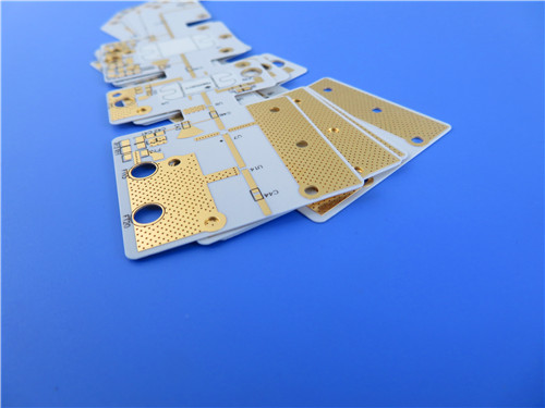
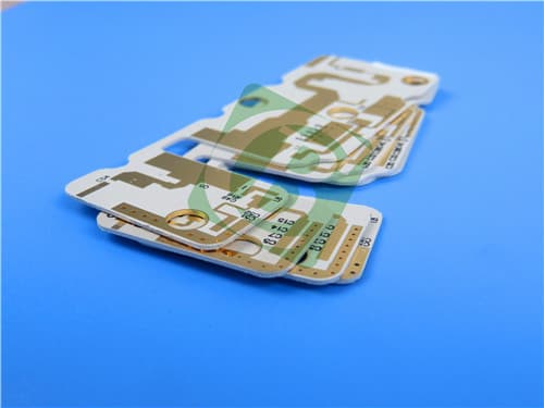
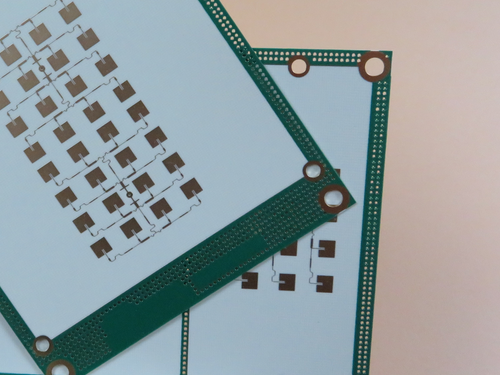
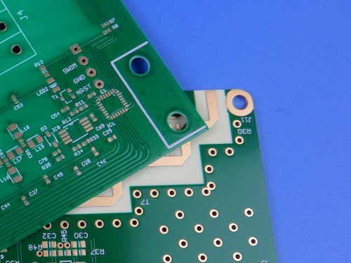
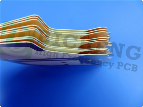
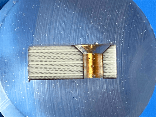
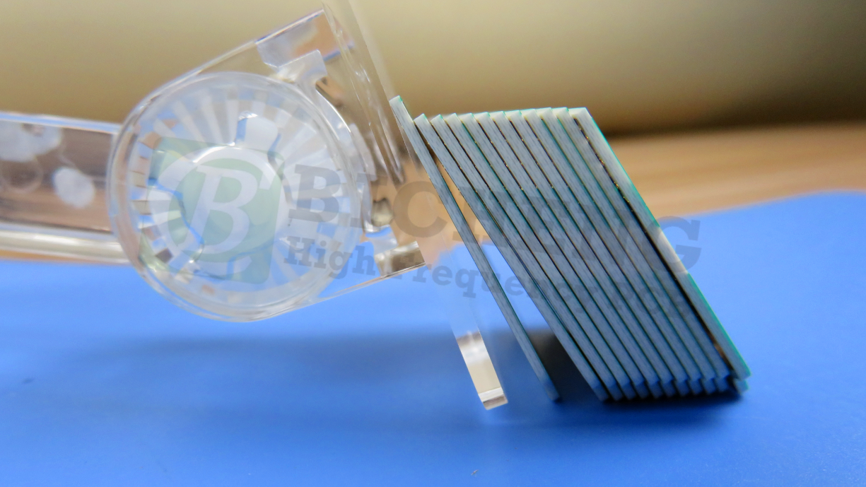
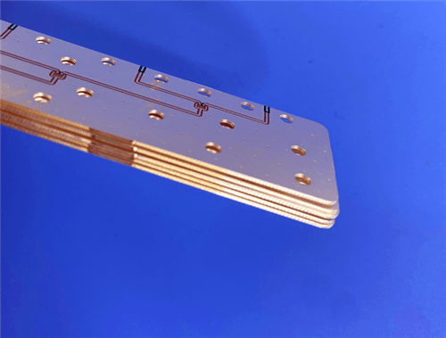
This 4-layer rigid PCB combines RO3003 as the top core with FR-4 materials in a hybrid stack-up, optimizing both RF performance and mechanical rigidity for cost-effective, high-reliability applications.
2. Key Features of RO3003
Dielectric constant of 3.00 ± 0.04 at 10 GHz Dissipation factor of 0.0010 at 10 GHz Thermal coefficient of dielectric constant (TCDk) of -3 ppm/°C Low moisture absorption of 0.04% CTE in X-axis of 17 ppm/°C, Y-axis of 16 ppm/°C, Z-axis of 25 ppm/°C Thermal conductivity of 0.50 W/(m·K) Decomposition temperature (Td) of 500°C UL 94 V-0 flammability rating Lead-free process compatible
3. Benefits of RO3003 PCB
Stable electrical and mechanical properties across temperature variations Excellent dimensional stability matched to copper Reliable plated through-hole performance in thermal cycling Compatible with standard PTFE circuit board processing techniques Enables hybrid multilayer designs with different dielectric constants without warpage Low loss for high-frequency signal integrity
4. RO3003 PCB Construction Details
| Item | Specification |
|---|
| Base material | RO3003 (top core) + FR-4 (TG170) |
| Layer count | 4 layers |
| Board dimensions | 52mm x 77mm = 1PCS |
| Finished board thickness | 0.8 mm |
| Finished Cu weight | Outer layers: 1 oz (35 μm)
Inner layers: 0.5 oz (18 μm) |
| Surface finish | Immersion Silver |
| Top solder mask | Green, no legend |
| Bottom solder mask | No mask, no legend |
| 100% Electrical test | Used prior to shipment |
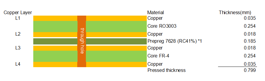
5. PCB Stackup (4-Layer Hybrid Rigid Structure)
L1 (Top Copper): 1 oz (0.035 mm) Core: RO3003 – 0.254 mm L2 (Inner Copper): 0.5 oz (0.018 mm) Prepreg: 7628 (RC41%) ×1 – 0.185 mm L3 (Inner Copper): 0.5 oz (0.018 mm) Core: FR-4 TG170 – 0.254 mm L4 (Bottom Copper): 1 oz (0.035 mm) Total Pressed Thickness: 0.799 mm
6. Primary Application Areas
Commercial microwave and RF circuits Microstrip and stripline designs Multilayer hybrid boards (PTFE + FR-4) Automotive radar systems Point-to-point digital radio antennas Satellite communication systems High-reliability aerospace and defense electronics
7. Quality Assurance
Artwork supplied: Gerber RS-274-X
Accepted standard: IPC-Class-2
Availability: Worldwide
8. RO3003 High Frequency Laminates Introduction
RO3003 is a ceramic-filled PTFE composite intended for use in commercial microwave and RF applications. The RO3000 series was designed to offer exceptional electrical and mechanical stability at competitive prices.
RO3003 laminates have mechanical properties that are consistent regardless of the dielectric constant selected. This allows designers to develop multilayer board designs using different dielectric constant materials for individual layers without encountering warpage or reliability problems.
The material exhibits a CTE in the X and Y axes of 17 ppm/°C, matched to that of copper, which provides excellent dimensional stability. The Z-axis CTE of 24 ppm/°C offers exceptional plated through-hole reliability, even in severe thermal environments. The dielectric constant versus temperature is very stable.
RO3003 laminates can be fabricated into printed circuit boards using standard PTFE circuit board processing techniques, with minor modifications as described in Rogers' fabrication guidelines.
9. Features and Benefits
Key Features
Dielectric constant: 3.00 ± 0.04 at 10 GHz Dissipation factor: 0.0010 at 10 GHz TCDk: -3 ppm/°C (-50 to 150°C) Moisture absorption: 0.04% CTE (X/Y/Z): 17 / 16 / 25 ppm/°C Td: 500°C Thermal conductivity: 0.50 W/(m/K) UL 94 V-0 flammability rating Lead-free process compatible
Benefits
Stable electrical performance over temperature Excellent dimensional stability matched to copper Reliable plated through-hole performance Compatible with standard PTFE processing Enables hybrid multilayer designs without warpage Low loss for high-frequency operation
10. RO3003 Data Sheet
| Property | Typical Value | Units | Conditions | Test Method |
|---|
| Dielectric Constant (process) | 3.00 ± 0.04 | – | 10 GHz / 23°C | IPC TM-650 2.5.5.5 |
| Dielectric Constant (design) | 3.00 | – | 8 GHz – 40 GHz | Differential Phase Length |
| Dissipation Factor | 0.0010 | – | 10 GHz / 23°C | IPC TM-650 2.5.5.5 |
| Thermal Coefficient of εr | -3 | ppm/°C | -50 to 150°C / 10 GHz | IPC TM-650 2.5.5.5 |
| Volume Resistivity | 10⁷ | MΩ·cm | Condition A | IPC TM-650 2.5.17.1 |
| Surface Resistivity | 10⁷ | MΩ | Condition A | IPC TM-650 2.5.17.1 |
| Moisture Absorption | 0.04 | % | D48/50 | IPC TM-650 2.6.2.1 |
| Thermal Conductivity | 0.50 | W/(m·K) | 50°C | ASTM D5470 |
| CTE - X | 17 | ppm/°C | -55 to 288°C | IPC TM-650 2.4.41 |
| CTE - Y | 16 | ppm/°C | -55 to 288°C | IPC TM-650 2.4.41 |
| CTE - Z | 25 | ppm/°C | -55 to 288°C | IPC TM-650 2.4.41 |
| Decomposition Temperature (Td) | 500 | °C TGA | – | ASTM D3850 |
| Density | 2.1 | g/cm³ | 23°C | ASTM D792 |
| Copper Peel Strength | 12.7 | lbs/in | 1 oz EDC after solder float | IPC TM-650 2.4.8 |
| Young's Modulus | 930 (X), 823 (Y) | MPa | 23°C | ASTM D638 |
| Dimensional Stability (MD/CMD) | -0.06 / 0.07 | mm/m | Condition A | IPC TM-650 2.2.4 |
| Flammability | V-0 | Class | – | UL 94 |
| Lead-Free Process Compatible | Yes | – | – | – |
11. Typical Applications
Commercial microwave and RF circuits Microstrip and stripline designs Multilayer hybrid boards (PTFE + FR-4) Automotive radar systems Point-to-point digital radio antennas Satellite communication systems High-reliability aerospace and defense electronics
12. Standard Thicknesses, Panel Sizes & Claddings
Standard Thicknesses – RO3003
| Thickness (inch) | Thickness (mm) | Tolerance |
|---|
| 0.005" | 0.13 mm | ±0.0005" |
| 0.010" | 0.25 mm | ±0.0007" |
| 0.020" | 0.51 mm | ±0.0010" |
| 0.030" | 0.76 mm | ±0.0015" |
| 0.060" | 1.52 mm | ±0.0030" |
Standard Panel Sizes
12" × 18" (305 mm × 457 mm) 24" × 18" (610 mm × 457 mm) 24" × 21" (610 mm × 533 mm) – for 0.005" and 0.010" RO3003
Standard Claddings – RO3003
Electrodeposited Copper Foil: ½ oz (18 μm), 1 oz (35 μm) Rolled Copper Foil: ½ oz (18 μm), 1 oz (35 μm)
Additional configurations including other thicknesses, panel sizes, and claddings are available upon request.
|