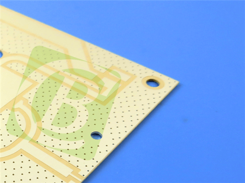
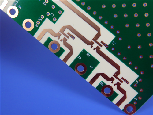
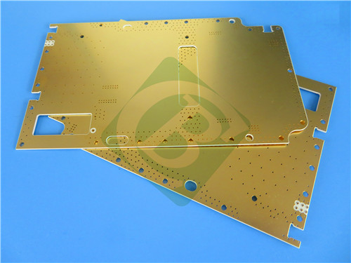
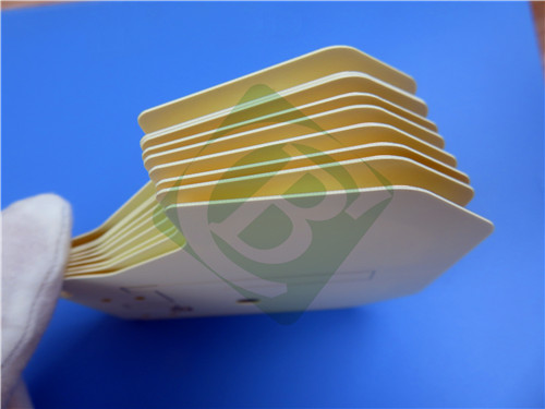
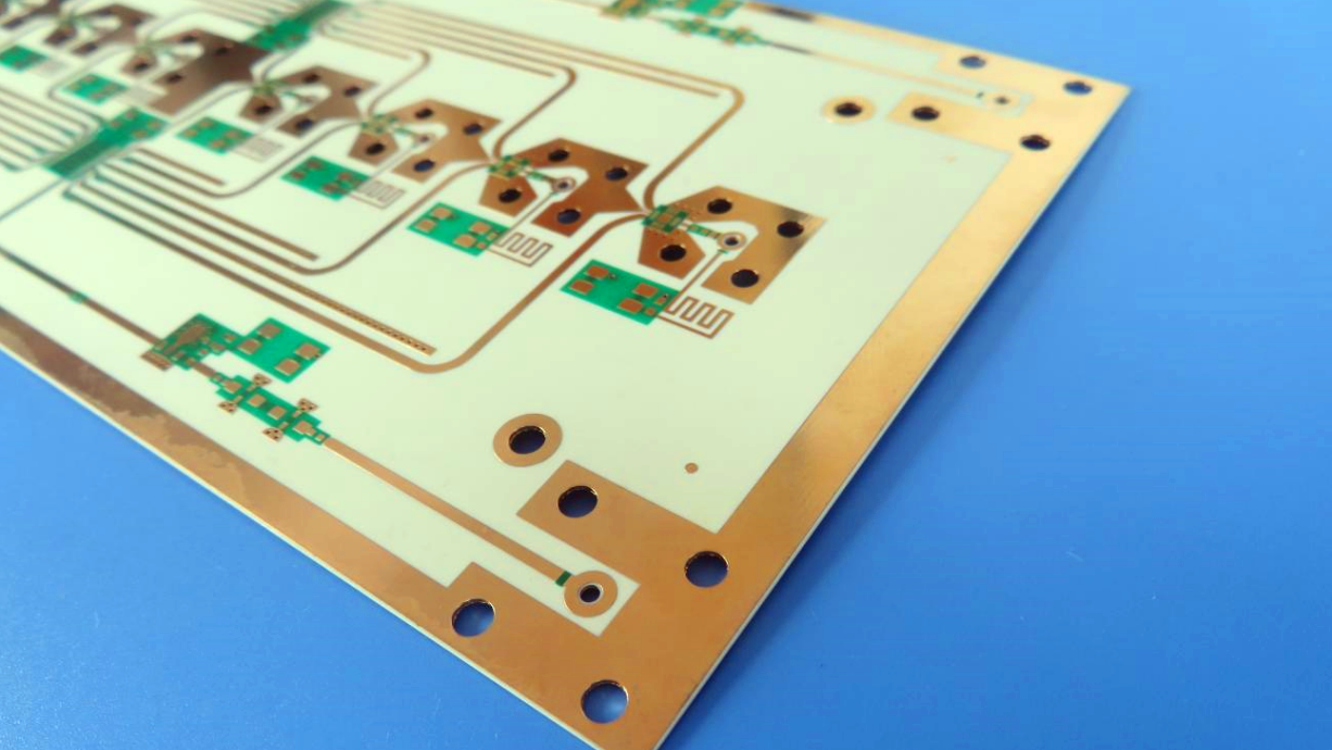
Rogers RO3210 4-Layer 1.36mm ENIG Immersion Silver PCB – High Mechanical Stability & RF Applications
1. Introduction to RO3210 PCB
Rogers RO3210 high frequency circuit materials are ceramic-filled laminates reinforced with woven fiberglass. These materials are engineered to offer exceptional electrical performance and mechanical stability at competitive prices. The RO3200 series was designed as an extension of the RO3000 series with one distinguishing characteristic – improved mechanical stability.
RO3210 laminates combine the surface smoothness of a non-woven PTFE laminate, for finer line etching tolerances, with the rigidity of a woven-glass PTFE laminate. These materials can be fabricated into printed circuit boards using standard PTFE circuit board processing techniques as described in Rogers' application notes.
The dielectric constant of RO3210 is 10.2 with a dissipation factor of 0.0027 at 10 GHz. This 4-layer rigid PCB is constructed with RO3210 as both top and bottom cores, bonded by RO4450F bondply, providing exceptional signal integrity, high dielectric constant, and low-loss performance for demanding RF, microwave, and millimeter wave applications.
2. Key Features of RO3210
Dielectric constant of 10.2 ± 0.50 at 10 GHz (process) / 10.8 (design) Dissipation factor of 0.0027 at 10 GHz Thermal coefficient of dielectric constant (TCDk) of -459 ppm/°C Low moisture absorption of <0.1% CTE in X/Y axes of 13 ppm/°C, Z-axis of 34 ppm/°C Thermal conductivity of 0.81 W/(m·K) Decomposition temperature (Td) of 500°C UL 94 V-0 flammability rating Lead-free process compatible Improved mechanical stability vs. RO3000 series Woven fiberglass reinforced for rigidity
3. Benefits of RO3210 PCB
Superior mechanical stability for demanding environments Surface smoothness enables finer line etching tolerances Combines PTFE electrical performance with woven-glass rigidity Compatible with standard PTFE circuit board processing techniques Stable electrical properties over wide frequency range Excellent dimensional stability Reliable plated through-hole performance Ideal for high-frequency, high-reliability applications
4. RO3210 PCB Construction Details
| Item | Specification |
|---|
| Base material | RO3210 (top and bottom cores) + RO4450F bondply |
| Layer count | 4 layers |
| Board dimensions | 95mm x 98mm = 1PCS |
| Finished board thickness | 1.36 mm (nominal) |
| Finished Cu weight | Outer layers: 1 oz (35 μm)
Inner layers: 0.5 oz (18 μm) |
| Surface finish | Immersion Silver + ENIG (selective) |
| Top solder mask | Green, white legend |
| Bottom solder mask | Green, no legend |
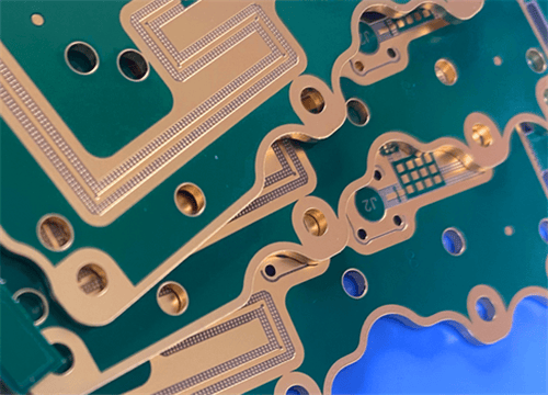
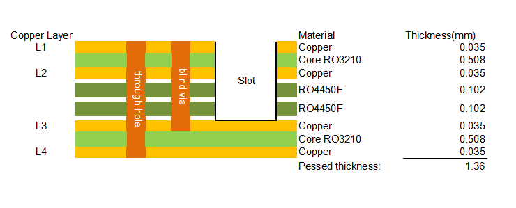
| Special features | Controlled depth slot (TOP to inner layer 1)
Blind vias (L1-L3) |
| 100% Electrical test | Used prior to shipment |
5. PCB Stackup (4-Layer Hybrid Rigid Structure)
L1 (Top Copper): 1 oz (0.035 mm) Core: RO3210 – 0.508 mm L2 (Inner Copper): 0.5 oz (0.035 mm) Bondply: RO4450F – 0.102 mm Bondply: RO4450F – 0.102 mm L3 (Inner Copper): 0.5 oz (0.035 mm) Core: RO3210 – 0.508 mm L4 (Bottom Copper): 1 oz (0.035 mm) Total Pressed Thickness: 1.36 mm
6. PCB Special Features
7. Primary Application Areas
Commercial microwave and RF circuits Microstrip and stripline designs High mechanical stability applications Automotive radar systems (high Dk) Satellite communication systems Point-to-point digital radio antennas High-reliability aerospace and defense electronics Power amplifiers and filters Base station antennas
8. Quality Assurance
Artwork supplied: Gerber RS-274-X Accepted standard: IPC-Class-2 (typical) Availability: Worldwide Manufactured under ISO 9002 certified quality system Fabrication according to Rogers' application note
9. RO3210 High Frequency Laminates – Product Introduction
RO3210 high frequency circuit materials are ceramic-filled laminates reinforced with woven fiberglass. These materials are engineered to offer exceptional electrical performance and mechanical stability at competitive prices.
The RO3200 series high frequency materials were designed as an extension of the RO3000 series with one distinguishing characteristic – improved mechanical stability. RO3210 laminates combine the surface smoothness of a non-woven PTFE laminate, for finer line etching tolerances, with the rigidity of a woven-glass PTFE laminate.
The dielectric constant of RO3210 is 10.2 with a dissipation factor of 0.0027. These materials can be fabricated into printed circuit boards using standard PTFE circuit board processing techniques as described in the application note "Fabrication Guidelines for RO3000 Series High Frequency Circuit Materials."
RO3200 series laminates are manufactured under an ISO 9002 certified quality system.
10. Features and Benefits
Key Features
| Property | Typical Value |
|---|
| Dielectric Constant (process) | 10.2 ± 0.50 @ 10 GHz |
| Dielectric Constant (design) | 10.8 @ 8-40 GHz |
| Dissipation Factor | 0.0027 @ 10 GHz |
| TCDk | -459 ppm/°C |
| CTE (X/Y) | 13 ppm/°C |
| CTE (Z) | 34 ppm/°C |
| Thermal Conductivity | 0.81 W/m/K |
| Td | 500°C |
| Density | 3.0 g/cm³ |
| Moisture Absorption | <0.1% |
| Copper Peel Strength | 11.0 pli |
| Flammability | V-0 |
| Lead-Free Compatible | Yes |
| Color | Off White |
Benefits
Improved mechanical stability for rugged applications Surface smoothness enables finer line etching tolerances Combines PTFE electrical performance with woven-glass rigidity Compatible with standard PTFE processing Stable electrical properties over wide frequency range Excellent dimensional stability (0.8 mm/m) High dielectric constant enables circuit size reduction
11. RO3210 Data Sheet
| Property | Typical Value | Direction | Units | Conditions | Test Method |
|---|
| Dielectric Constant, εr (Process) | 10.2 ± 0.50 | Z | – | 10 GHz / 23°C | IPC-TM-650 2.5.5.5 |
| Dielectric Constant, εr (Design) | 10.8 | Z | – | 8-40 GHz | Differential Phase Length |
| Dissipation Factor, tan δ | 0.0027 | Z | – | 10 GHz / 23°C | IPC-TM-650 2.5.5.5 |
| Thermal Coefficient of εr | -459 | Z | ppm/°C | 10 GHz / 0-100°C | IPC-TM-650 2.5.5.5 |
| Dimensional Stability | 0.8 | X,Y | mm/m | COND A | ASTM D257 |
| Volume Resistivity | 10³ | – | MΩ·cm | COND A | IPC-TM-650 2.5.17.1 |
| Surface Resistivity | 10³ | – | MΩ | COND A | IPC-TM-650 2.5.17.1 |
| Tensile Modulus | 579 (MD), 517 (CMD) | – | kpsi | 23°C | ASTM D638 |
| Water Absorption | <0.1 | – | % | D24/23 | IPC-TM-650 2.6.2.1 |
| Specific Heat | 0.79 | – | J/g/K | – | Calculated |
| Thermal Conductivity | 0.81 | – | W/m/K | 80°C | ASTM C518 |
| CTE (-55 to 288°C) | 13 (X,Y), 34 (Z) | – | ppm/°C | 23°C/50% RH | IPC-TM-650 2.4.41 |
| Td | 500 | – | °C | TGA | ASTM D3850 |
| Density | 3.0 | – | g/cm³ | – | – |
| Copper Peel Strength | 11.0 | – | pli | 1 oz EDC after solder float | IPC-TM-2.4.8 |
| Flammability | V-0 | – | Class | – | UL 94 |
| Lead-Free Process Compatible | Yes | – | – | – | – |
| Color | Off White | – | – | – | – |
12. Typical Applications
Commercial microwave and RF circuits Microstrip and stripline designs High mechanical stability applications Automotive radar systems Satellite communication systems Point-to-point digital radio antennas High-reliability aerospace and defense electronics Power amplifiers and filters Base station antennas Millimeter wave applications
13. Standard Thicknesses, Panel Sizes & Claddings
Standard Thicknesses – RO3210
| Thickness (inch) | Thickness (mm) |
|---|
| 0.025" | 0.64 mm |
| 0.050" | 1.28 mm |
Standard Panel Sizes
Standard Copper Claddings
½ oz (17 μm) electrodeposited copper foil (HH/HH) 1 oz (35 μm) electrodeposited copper foil (H1/H1) 2 oz (70 μm) electrodeposited copper foil (H2/H2)
Other claddings may be available. Contact customer service.
|