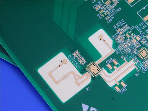
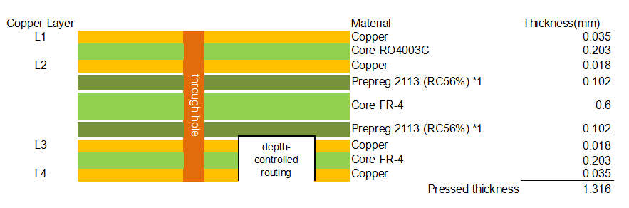
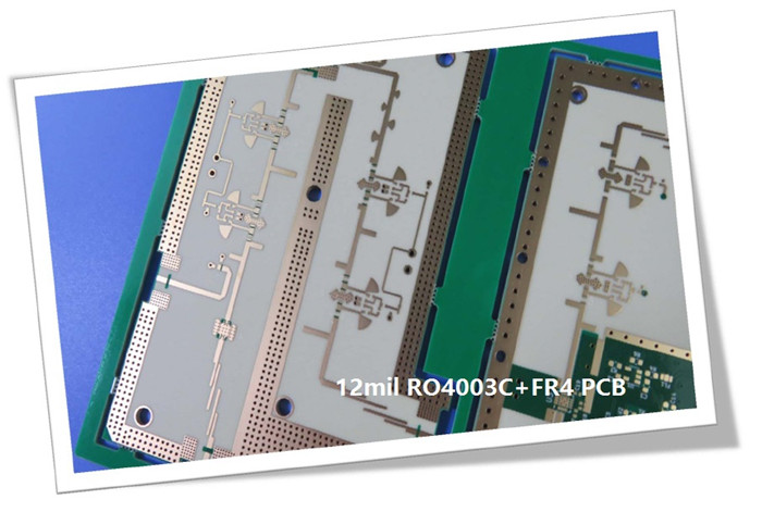
Rogers RO4003C and FR-4 4-Layer 1.4mm High Frequency RF Microwave PCB ENIG1.Introduction to RO4003C + FR-4 4-Layer Hybrid PCB This 4-layer rigid hybrid PCB is constructed with Rogers RO4003C and High Tg FR-4 (TG175) as the base materials. RO4003C hydrocarbon ceramic laminates are designed to offer superior high frequency performance and low cost circuit fabrication. The result is a low loss material which can be fabricated using standard epoxy/glass (FR-4) processes offered at competitive prices. RO4003C material possesses the properties needed by designers of RF microwave circuits, matching networks, and controlled impedance transmission lines. Low dielectric loss allows RO4003C to be used in many applications where higher operating frequencies limit the use of conventional circuit board laminates. The board features immersion gold (ENIG) surface finish with 2 microinches gold thickness, green solder mask, white silkscreen, 25μm via plating thickness, IPC-Class-3 quality standard, and controlled depth routing. The finished board thickness is 1.4mm with board dimensions of 200mm x 115mm. 2.Key Features of RO4003C Dielectric constant (process): 3.38 ±0.05 at 10 GHz / 23°C 3.Benefits of This 4-Layer Hybrid PCB RO4003C hydrocarbon ceramic provides low dielectric loss for high frequency performance 4.RO4003C + FR-4 4-Layer Hybrid PCB Construction Details
5.PCB Stackup (4-Layer Rigid Structure) Copper layer 1 (Top): 1 oz (Finished copper) Finished board thickness: 1.4mm
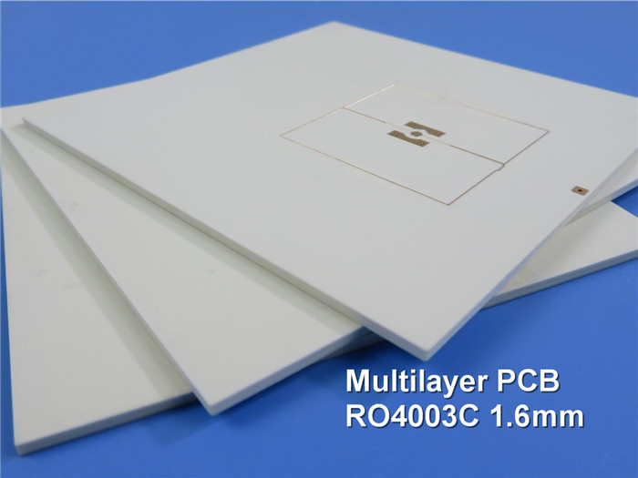
6.Primary Application Areas Cellular base station antennas and power amplifiers 7.Quality Assurance Artwork supplied: Gerber RS-274-X 8.RO4003C High-Frequency Laminate – Product Introduction RO4000 hydrocarbon ceramic laminates are designed to offer superior high frequency performance and low cost circuit fabrication. The result is a low loss material which can be fabricated using standard epoxy/glass (FR-4) processes offered at competitive prices. The selection of laminates typically available to designers is significantly reduced once operational frequencies increase to 500 MHz and above. RO4000 material possesses the properties needed by designers of RF microwave circuits, matching networks, and controlled impedance transmission lines. Low dielectric loss allows RO4000 series material to be used in many applications where higher operating frequencies limit the use of conventional circuit board laminates. The temperature coefficient of dielectric constant is among the lowest of any circuit board material, and the dielectric constant is stable over a broad frequency range, making it an ideal substrate for broadband applications. RO4000 material's thermal coefficient of expansion (CTE) is similar to that of copper which allows the material to exhibit excellent dimensional stability, a property needed for mixed dielectric multi-layer boards constructions. The low Z-axis CTE of RO4000 laminates provides reliable plated through-hole quality, even in severe thermal shock applications. RO4000 series material has a Tg of >280°C (536°F) so its expansion characteristics remain stable over the entire range of circuit processing temperatures. RO4000 series laminates can easily be fabricated into printed circuit boards using standard FR-4 circuit board processing techniques. Unlike PTFE based high performance materials, RO4000 series laminates do not require specialized via preparation processes such as sodium etch. This material is a rigid, thermoset laminate that is capable of being processed by automated handling systems and scrubbing equipment used for copper surface preparation. RO4003C laminates are currently offered in various configurations utilizing both 1080 and 1674 glass fabric styles, with all configurations meeting the same laminate electrical performance specification. 9.Features and Benefits of RO4003C
Benefits: 10.RO4003C Data Sheet
11.Some Typical Applications Cellular base station antennas and power amplifiers 12.What is a Hybrid PCB (High-Frequency Hybrid PCB)? A hybrid PCB, also known as a mixed dielectric PCB, combines two or more different types of laminate materials in a single board construction. In this product, Rogers RO4003C (high-frequency hydrocarbon ceramic) is combined with High Tg FR-4 (TG175). This allows designers to place high-frequency circuits on RO4003C layers for optimal RF performance while using lower-cost FR-4 for non-critical layers, balancing performance and cost. Advantages of Hybrid PCBs: Disadvantages of Hybrid PCBs: 13.Fabrication Guidelines for RO4003C: Storage: Fully clad RO4003C laminates should be stored at room temperature between 50-90°F (10-32°C). Inner Layer Preparation: RO4003C laminates are compatible with many pinned and pinless tooling systems. Copper surfaces can be prepared for photo imaging using chemical or mechanical processes. RO4003C materials are compatible with most liquid and dry film photo-resists and can be processed through develop, etch, and strip (DES) systems typically used to process FR-4 materials. Multi-Layer Bonding: RO4003C laminates are compatible with many thermosetting and thermoplastic adhesive systems. Drilling: Standard entry and exit materials can be used. Drilling speeds greater than 500 surface feet per minute (SFM) should be avoided. Standard geometry drills are preferred. Hole wall roughness ranging from 8 to 25 μm is expected. PTH Processing: Desmear is typically not required for double-sided boards as the high Tg (>280°C) minimizes smear. If desmear is required, alkaline permanganate or CF4/O2 plasma process may be used. RO4003C materials do not require special treatments prior to metallization. Final Metal Finishes: RO4003C laminates are compatible with OSPs, HASL, and most chemically deposited or electroplated finishes including ENIG. Routing: RO4003C laminates are routed using carbide tools and conditions typical to processing traditional epoxy/glass materials. |
Get a Quick Quote
Fill in the form below and our engineers will reply within 24 hours with technical specifications and pricing for Rogers RO4003C + FR-4 4-Layer 1.4mm Hybrid PCB.
.jpg)