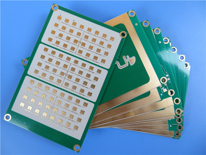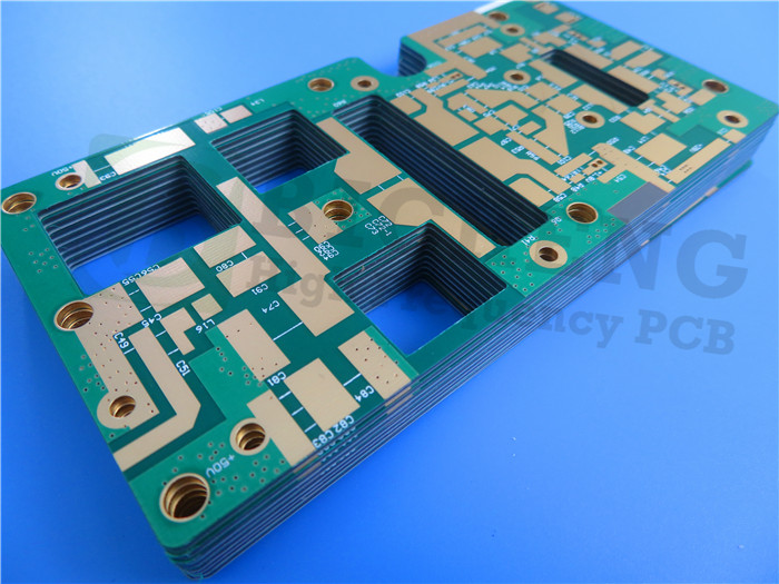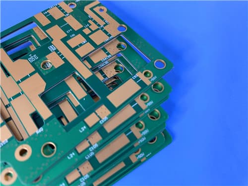
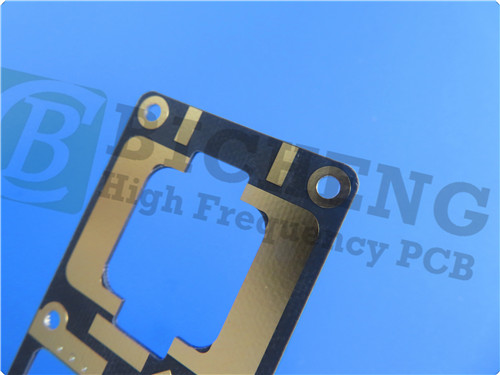
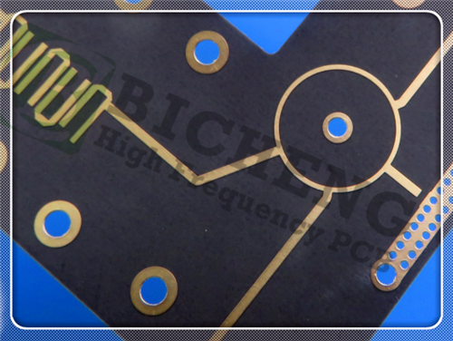
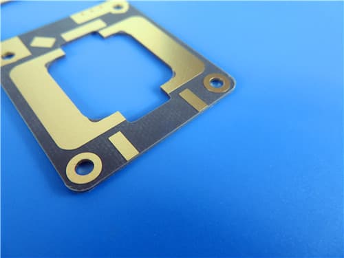
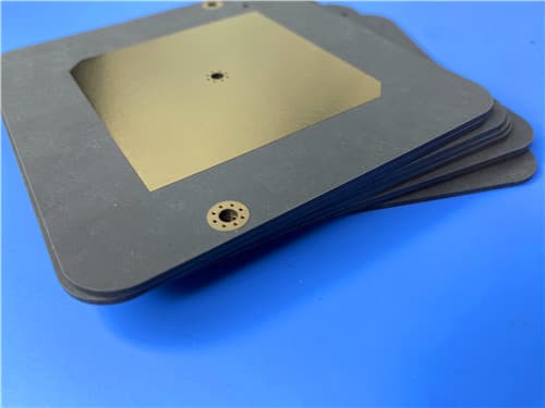
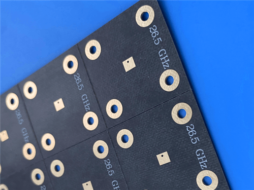
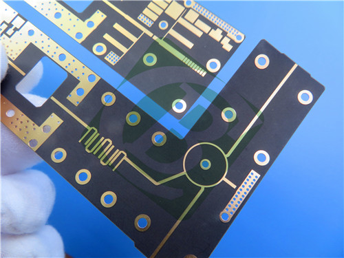
Rogers RT/duroid 5880 FR-4 4-Layer 1.0mm High Frequency RF Microwave PCB ENIG1.Introduction to RT/duroid 5880 + FR-4 4-Layer Hybrid PCB This 4-layer copper (6-layer structure) rigid hybrid PCB is constructed with Rogers RT/duroid 5880 and High Tg FR-4 as the base materials. RT/duroid 5880 is a glass microfiber reinforced PTFE composite designed for exacting stripline and microstrip circuit applications. The randomly oriented microfibers result in exceptional dielectric constant uniformity. The dielectric constant of RT/duroid 5880 laminates is uniform from panel to panel and is constant over a wide frequency range. Its low dissipation factor extends the usefulness of RT/duroid 5880 laminates to Ku-band and above. The board features immersion gold (ENIG) surface finish with 2 microinches gold thickness, blue solder mask, white silkscreen, 25μm via plating thickness, IPC-Class-3 quality standard, and controlled depth routing. The finished board thickness is 1.0mm with board dimensions of 90mm x 80mm. 2.Key Features of RT/duroid 5880 Dielectric constant (process): 2.20 ±0.02 at 10 GHz / 23°C 3.Benefits of This 4-Layer Hybrid PCB RT/duroid 5880 glass microfiber reinforced PTFE provides exceptional dielectric constant uniformity 4.RT/duroid 5880 + FR-4 4-Layer Hybrid PCB Construction Details
5.PCB Stackup (4-Layer Rigid PCB) L1 Copper: 0.035 mm Pressed thickness: 0.954 mm
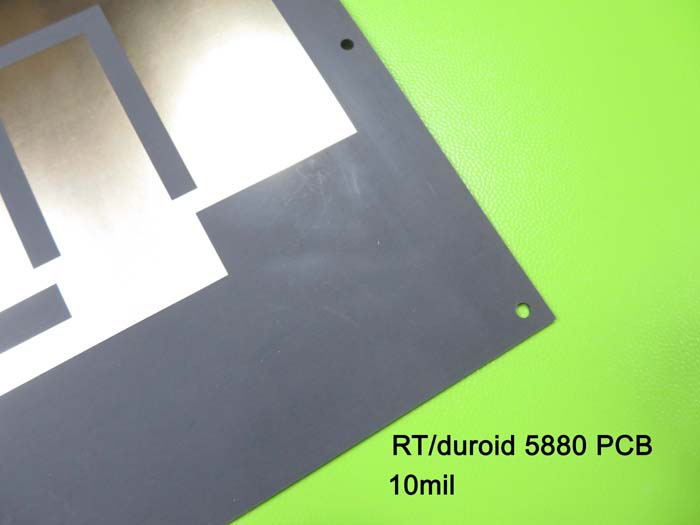
6.Primary Application Areas Stripline and microstrip circuit applications 7.Quality Assurance Artwork supplied: Gerber RS-274-X 8.RT/duroid 5880 High-Frequency Laminate – Product Introduction RT/duroid 5880 glass microfiber reinforced PTFE composites are designed for exacting stripline and microstrip circuit applications. The randomly oriented microfibers result in exceptional dielectric constant uniformity. The dielectric constant of RT/duroid 5880 laminates is uniform from panel to panel and is constant over a wide frequency range. Its low dissipation factor extends the usefulness of RT/duroid 5880 laminates to Ku-band and above. RT/duroid 5880 laminates are easily cut, sheared and machined to shape. They are resistant to all solvents and reagents, hot or cold, normally used in etching printed circuits or in plating edges and holes. Normally supplied as a laminate with electrodeposited copper of ½ to 2 ounces per square foot on both sides, RT/duroid 5880 composites can also be clad with rolled copper foil for more critical electrical applications. Cladding with aluminum, copper or brass plate may also be specified. 9.Features and Benefits of RT/duroid 5880
Benefits: RT/duroid 5880 Data Sheet
11.Some Typical Applications Stripline and microstrip circuit applications 12.What is Controlled Depth Routing? Controlled depth routing is a precision machining technique used in PCB fabrication to route or mill to a specific depth without cutting through the entire board thickness. This allows for the creation of cavities, step cuts, or partial cutouts in the PCB. In this product, controlled depth routing is incorporated for precise mechanical features. 13.Fabrication Guidelines for RT/duroid 5880: Storage: RT/duroid laminates can be stored indefinitely at normal ambient room temperatures (65°F to 85°F, 18°C to 30°C) and humidity levels. At room temperature, the dielectric materials are inert to high humidity. Handling: PTFE-based materials are softer than most other rigid printed wiring board laminates and are more susceptible to handling damage. Gloves should be worn when handling panels. Drilling: Carbide drills should be used. Standard style drills with an included lip angle of 130° are recommended. Optimum tool surface speed is 150 to 250 surface feet per minute with infeed rates of 0.0015" to 0.0025" per revolution. Drilled holes must be treated prior to deposition of a conductive seed layer. Sodium treatment is the preferred option for treating RT/duroid 5880 materials. Hole Preparation: Sodium treatments consist of a highly reactive sodium napthalene complex in glycol ether solution. They are very effective at making PTFE surfaces wettable prior to metal deposition. Plasma treatment may be used for direct metallization processes. Metallization: Low to regular deposition rate electroless copper processes may be used once the PTFE surface has been properly treated. Final Metal Finishes: All final metal surface options (i.e. HASL, Sn, Sn/Pb, Ni/Au, Ag, OSP, etc.) can be applied using normal procedures. |

Get a Quick Quote
Fill in the form below and our engineers will reply within 24 hours with technical specifications and pricing for Rogers RT/duroid 5880 + FR-4 4-Layer 1.0mm Hybrid PCB.
.jpg)
.jpg)
.jpg)