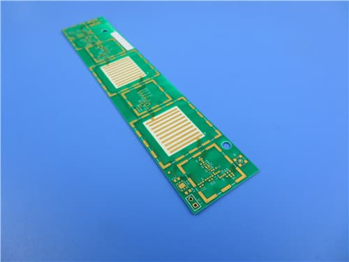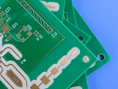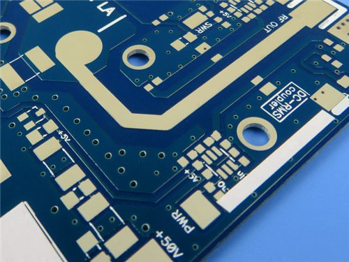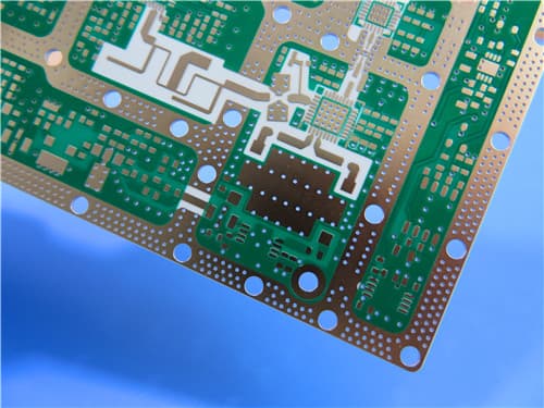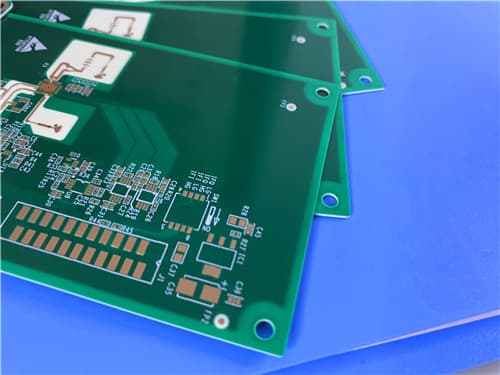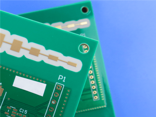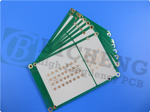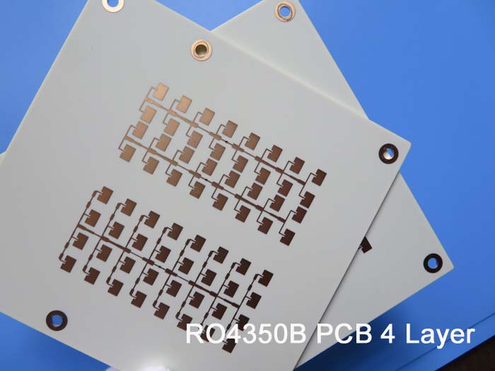
Rogers RO4350B FR-4 8-Layer 1.553mm High Frequency RF Microwave PCB ENIG1.Introduction to RO4350B + FR-4 8-Layer Hybrid PCB This 8-layer rigid hybrid PCB is constructed with Rogers RO4350B on the top and bottom layers and FR-4 Tg180 in the middle. RO4350B hydrocarbon ceramic laminates are designed to offer superior high frequency performance and low cost circuit fabrication. The result is a low loss material which can be fabricated using standard epoxy/glass (FR-4) processes offered at competitive prices. RO4350B material possesses the properties needed by designers of RF microwave circuits, matching networks, and controlled impedance transmission lines. The board features ENIG surface finish, green solder mask, white silkscreen, 25μm via plating thickness, IPC-Class-3 quality standard, metal cladding, blind vias from layer 1 to layer 2, buried vias from layer 5 to layer 6, and resin plugged vias. The finished board thickness is 1.553mm with board dimensions of 120mm x 30mm.
2.Key Features of RO4350B Dielectric constant (process): 3.48 ±0.05 at 10 GHz / 23°C 3.Benefits of This 8-Layer Hybrid PCB RO4350B hydrocarbon ceramic provides low dielectric loss for high frequency performance 4.RO4350B + FR-4 8-Layer Hybrid PCB Construction Details
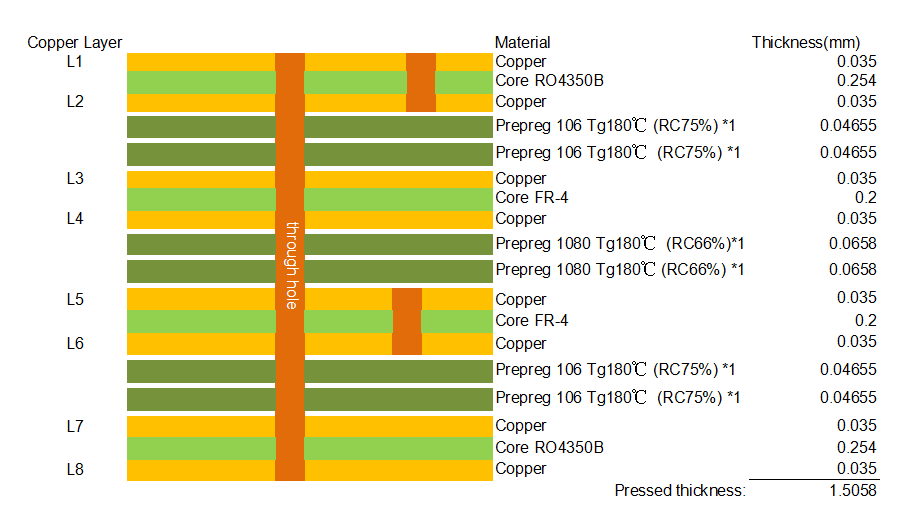
5.PCB Stackup (8-Layer Rigid Structure) L1 Copper: 0.035 mm Pressed thickness: 1.5058 mm
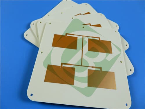
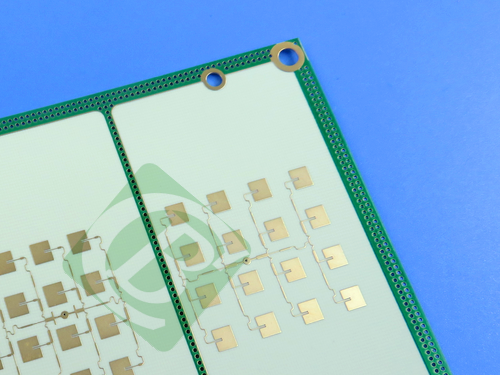
6.Primary Application Areas Cellular base station antennas and power amplifiers 7.Quality Assurance Type of artwork supplied: Gerber RS-274-X 8.RO4350B High-Frequency Laminate – Product Introduction RO4000 hydrocarbon ceramic laminates are designed to offer superior high frequency performance and low cost circuit fabrication. The result is a low loss material which can be fabricated using standard epoxy/glass (FR-4) processes offered at competitive prices. RO4350B laminates utilize RoHS compliant flame-retardant technology for applications requiring UL 94V-0 certification. RO4000 material possesses the properties needed by designers of RF microwave circuits, matching networks, and controlled impedance transmission lines. Low dielectric loss allows RO4000 series material to be used in many applications where higher operating frequencies limit the use of conventional circuit board laminates. The temperature coefficient of dielectric constant is among the lowest of any circuit board material, and the dielectric constant is stable over a broad frequency range, making it an ideal substrate for broadband applications. RO4000 material's thermal coefficient of expansion (CTE) is similar to that of copper which allows the material to exhibit excellent dimensional stability, a property needed for mixed dielectric multi-layer boards constructions. The low Z-axis CTE of RO4000 laminates provides reliable plated through-hole quality, even in severe thermal shock applications. RO4000 series material has a Tg of >280°C (536°F) so its expansion characteristics remain stable over the entire range of circuit processing temperatures. RO4000 series laminates can easily be fabricated into printed circuit boards using standard FR-4 circuit board processing techniques. Unlike PTFE based high performance materials, RO4000 series laminates do not require specialized via preparation processes such as sodium etch. 9.Features and Benefits of RO4350B
Benefits: 10.RO4350B Data Sheet (Electrical & Mechanical)
11.Some Typical Applications Cellular base station antennas and power amplifiers 12.What are Blind Vias and Buried Vias? Blind Vias: Blind vias connect an outer layer to one or more inner layers but do not go through the entire board thickness. In this product, blind vias are used from layer 1 to layer 2 (L1-L2). Blind vias save space on outer layers and improve signal integrity by reducing stub effects. Buried Vias: Buried vias are located entirely within the inner layers and are not visible from the outer surfaces. In this product, buried vias are used from layer 5 to layer 6 (L5-L6). Buried vias allow for higher routing density and free up space on outer layers for component placement. Resin Plug: Resin plug is a process where vias are filled with resin to create a flat surface for stacking or component placement, improving reliability and preventing solder wicking. Metal Cladding: Metal cladding provides EMI shielding, improved thermal dissipation, and enhanced mechanical robustness at the board edges. 13.Fabrication Guidelines for RO4350B : Storage: Fully clad RO4350B laminates should be stored at room temperature between 50-90°F (10-32°C). Inner Layer Preparation: RO4350B materials are compatible with most liquid and dry film photo-resists and can be processed through develop, etch, and strip (DES) systems. Multi-Layer Bonding: RO4350B laminates are compatible with many thermosetting and thermoplastic adhesive systems. Drilling: Standard entry/exit materials, drilling speeds greater than 500 SFM should be avoided. Hole wall roughness 8-25 μm. PTH Processing: Desmear typically not required; RO4350B does not require special treatments prior to metallization. Final Metal Finishes: Compatible with OSPs, HASL, ENIG, etc. |
Get a Quick Quote
Fill in the form below and our engineers will reply within 24 hours with technical specifications and pricing for Rogers RO4350B + FR-4 8-Layer 1.553mm Hybrid PCB.