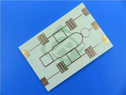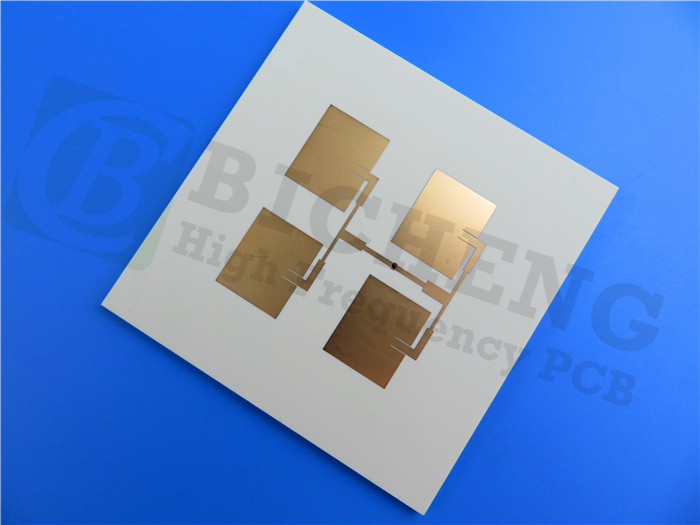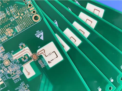
Rogers RO4533 2-Layer 0.6mm Immersion Gold PCB – Antenna Grade Applications1. Introduction to Rogers RO4533 PCB Rogers RO4533 laminates are ceramic-filled, glass-reinforced hydrocarbon based material set, providing the controlled dielectric constant, low loss performance and excellent passive intermodulation response required for mobile infrastructure microstrip antenna applications. RO4533 laminates are fully compatible with conventional FR-4 and high temperature lead-free solder processing. These laminates do not require special treatment needed on traditional PTFE-based laminates for plated through-hole preparation. It is an affordable alternative to more conventional PTFE antenna technologies, thus allowing designers to optimize the price and performance of their antennas. Moreover, RO4533 laminates are available halogen-free to meet the most stringent "green" standards. The resin systems of RO4533 dielectric materials are designed to provide the necessary properties for ideal antenna performance. The coefficients of thermal expansion (CTEs) in both the X and Y directions are similar to that of copper. The good CTE match reduces stresses in the printed circuit board antenna. The typical glass transition temperature of RO4533 materials exceeds 280°C (536°F), leading to a low z-axis CTE and excellent plated through-hole reliability. This 2-layer rigid PCB is constructed entirely with Rogers RO4533 as the core material, making it ideal for cellular infrastructure base station antennas and WiMAX antenna networks.
2. Key Features of Rogers RO4533 PCB Dielectric constant of 3.3 at 10 GHz (±0.08) Dissipation factor of 0.0020 at 2.5 GHz and 0.0025 at 10 GHz X-axis CTE of 13 ppm/°C, Y-axis CTE of 11 ppm/°C, Z-axis CTE of 37 ppm/°C Tg > 280°C Low moisture absorption of 0.02% Thermal conductivity of 0.6 W/(m·K) Low PIM performance better than -157 dBc (typical) Halogen-free available 3. Benefits of Rogers RO4533 PCB Low loss, low Dk and low PIM response for wide range of application use Thermoset resin system compatible with standard PCB fabrication (FR-4 processes) Excellent dimensional stability for greater yield on larger panel sizes Uniform mechanical properties for maintaining mechanical form during handling High thermal conductivity for improved power handling Good CTE match with copper reduces stresses in PCB antenna Low z-axis CTE and excellent plated through-hole reliability No special via preparation required (no sodium etch) Affordable alternative to PTFE antenna technologies 4. Rogers RO4533 PCB Construction Details
5. PCB Stackup (2-Layer Rigid Structure) Copper_layer_1 - 35 μm (1 oz) Rogers RO4533 Core - 0.508 mm (20 mil) Copper_layer_2 - 35 μm (1 oz) 6. PCB Statistics Components: 36 Total Pads: 28 Thru Hole Pads: 18 Top SMT Pads: 10 Bottom SMT Pads: 0 Vias: 17 Nets: 2 7. Primary Application Areas Cellular infrastructure base station antennas WiMAX antenna networks Mobile infrastructure microstrip antenna applications 8.Quality Assurance Type of artwork supplied: Gerber RS-274-X Accepted standard: IPC-Class-3 Availability: Worldwide 9. Rogers RO4533 Antenna Grade Laminate – Product Introduction RO4500 Series High Frequency Laminates are cost/performance materials from Rogers Corporation, specifically engineered and manufactured to meet the specific demands of the antenna markets. RO4533 laminates extend the capabilities of the successful RO4000 product series into antenna applications. This ceramic-filled, glass-reinforced hydrocarbon based material set provides the controlled dielectric constant, low loss performance and excellent passive intermodulation response required for mobile infrastructure microstrip antenna applications. As with all RO4000 high frequency laminates, RO4500 laminates are fully compatible with conventional FR-4 and high temperature lead-free solder processing. These laminates do not require special treatment needed on traditional PTFE-based laminates for plated through-hole preparation. This product series is an affordable alternative to more conventional PTFE antenna technologies, thus allowing designers to optimize the price and performance of their antennas. Moreover, RO4533 laminates are available halogen-free to meet the most stringent "green" standards. The resin systems of RO4500 dielectric materials are designed to provide the necessary properties for ideal antenna performance. The coefficients of thermal expansion (CTEs) in both the X and Y directions are similar to that of copper. The good CTE match reduces stresses in the printed circuit board antenna. The typical glass transition temperature of RO4500 materials exceeds 280°C (536°F), leading to a low z-axis CTE and excellent plated through-hole reliability. These properties, in combination with a dimensional stability value of less than 0.05%, make RO4500 laminates an excellent candidate for printed circuit antenna applications. RO4500 materials also provide increased thermal conductivity over equivalent PTFE/woven glass materials, allowing for design of antennas with increased power handling capability. In addition to these excellent thermo-mechanical properties, RO4500 laminates embody electrical characteristics that antenna designers need. The laminates have a dielectric constant (Dk) ranging from 3.3 to 3.5 (±0.08) and a loss tangent (Df) of 0.0020 to 0.0037 measured at 2.5 GHz. These values allow antenna designers to realize substantial gain values while minimizing signal loss. Materials are available with demonstrated low PIM performance, with values better than -155 dBc using two 43 dBm swept tones at 1900 MHz.
10. Features and Benefits Summary
11. Rogers RO4533 Data Sheet
12. Some Typical Applications Cellular infrastructure base station antennas WiMAX antenna networks Mobile infrastructure microstrip antenna applications 13. Standard Thicknesses, Panel Sizes & Claddings Standard Thicknesses (RO4533)
Standard Panel Sizes 24" x 18" (610 x 457 mm) 24" x 21" (610 x 533 mm) 24" x 36" (610 x 915 mm) 48" x 36" (1219 x 915 mm) Note: Additional panel sizes available. Standard Claddings Electrodeposited Copper Foil: ½ oz (18 μm), 1 oz (35 μm) |
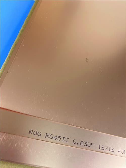
Get a Quick Quote
Fill in the form below and our engineers will reply within 24 hours with technical specifications and pricing for Rogers RO4533 2-Layer 0.6mm Immersion Gold PCB.
.jpg)