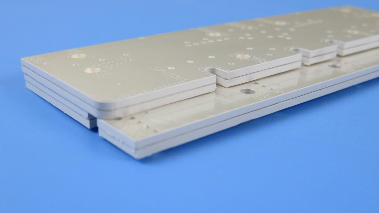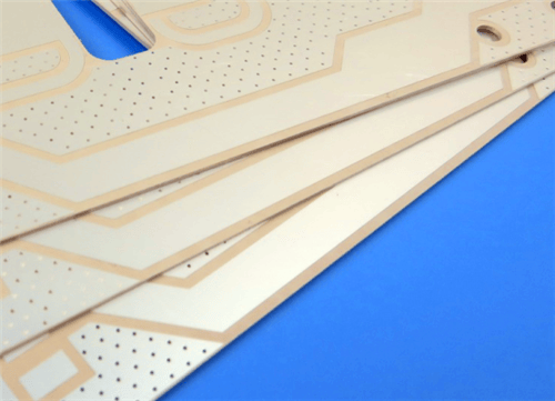
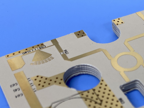
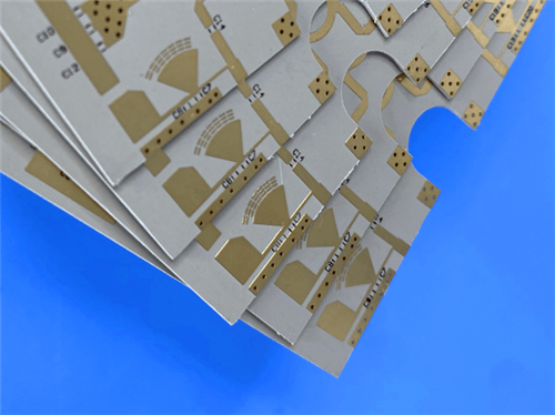
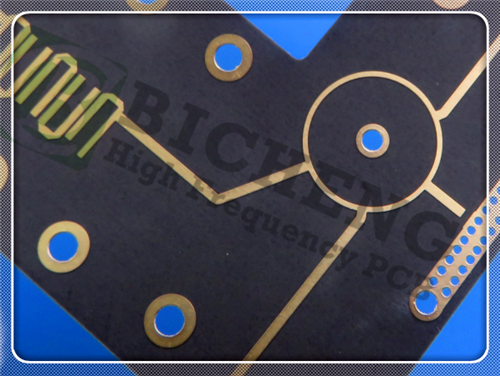
Rogers RT/duroid 6006 2-Layer 0.4mm Immersion Silver PCB – High Dk Microwave Applications1. Introduction to Rogers RT/duroid 6006 PCB Rogers RT/duroid 6006 laminates are ceramic-PTFE composites designed for electronic and microwave circuit applications requiring a high dielectric constant. They provide high dielectric constants (Dk) to enable circuit size reduction. These materials are low loss, ideal for operating at X-band or below. Additionally, their tight Dk and thickness control deliver repeatable circuit performance. RT/duroid 6006 microwave laminates feature ease of fabrication and stability in use. They have tight dielectric constant and thickness control, low moisture absorption, and good thermal mechanical stability. This 2-layer rigid PCB is constructed entirely with Rogers RT/duroid 6006 as the core material, making it ideal for patch antennas, satellite communications systems, power amplifiers, and ground radar warning systems.
2. Key Features of Rogers RT/duroid 6006 PCB Rogers RT/duroid 6006 ceramic-PTFE composites Dk of 6.15 ± 0.15 at 10 GHz/23°C Dissipation factor of 0.0027 at 10 GHz/23°C Td > 500°C (TGA) Moisture absorption of 0.05% CTE X-axis: 47 ppm/°C, Y-axis: 34 ppm/°C, Z-axis: 117 ppm/°C Clad with standard and reverse treated electrodeposited copper foil 3. Benefits of Rogers RT/duroid 6006 PCB High dielectric constant for circuit size reduction Low loss, ideal for operating at X-band or below Tight εr and thickness control for repeatable circuit performance Low moisture absorption Reliable plated through-holes in multi-layer boards Ease of fabrication and stability in use Good thermal mechanical stability 4.Rogers RT/duroid 6006 PCB Construction Details
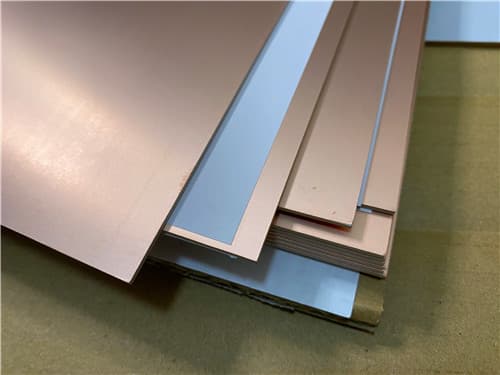
5. PCB Stackup (2-Layer Rigid Structure) Copper_layer_1 - 35 μm (1 oz) RT/duroid 6006 Core - 0.254 mm (10 mil) Copper_layer_2 - 35 μm (1 oz) 6. PCB Statistics Components: 46 Total Pads: 64 Thru Hole Pads: 26 Top SMT Pads: 38 Bottom SMT Pads: 0 Vias: 41 Nets: 2 7. Primary Application Areas Patch antennas Satellite communications systems Power amplifiers Aircraft collision avoidance systems Ground radar warning systems 8.Quality Assurance Type of artwork supplied: Gerber RS-274-X (typical, not explicitly stated in source) Accepted standard: IPC-Class-3 Availability: Worldwide 9. Rogers RT/duroid 6006 Ceramic-PTFE Laminate – Product Introduction RT/duroid 6006 microwave laminates are ceramic-PTFE composites designed for electronic and microwave circuit applications requiring a high dielectric constant. RT/duroid 6006 laminate is available with a dielectric constant value of 6.15. RT/duroid 6006 microwave laminates feature ease of fabrication and stability in use. They have tight dielectric constant and thickness control, low moisture absorption, and good thermal mechanical stability. RT/duroid 6006 laminates are supplied clad on both sides with 1/2 oz. to 2 oz./ft² (18 to 70 μm) standard and reverse treated electrodeposited copper foil. Thick aluminum, brass, or copper plate on one side may be specified. Standard tolerance dielectric thicknesses of 0.010", 0.025", 0.050", 0.075", and 0.100" (0.254, 0.635, 1.270, 1.905, 2.54 mm) are available. When ordering RT/duroid 6006 laminates, it is important to specify dielectric thickness and weight of copper foil required.
10. Features and Benefits Summary
11. Rogers RT/duroid 6006 Data Sheet
12. Some Typical Applications Patch antennas Satellite communications systems Power amplifiers Aircraft collision avoidance systems Ground radar warning systems 13. Standard Thicknesses, Panel Sizes & Claddings Standard Thicknesses
Standard Panel Sizes 10" x 10" (254 mm x 254 mm) 10" x 20" (254 mm x 508 mm) 18" x 12" (457 mm x 305 mm) Note: Additional panel sizes available. Standard Claddings Electrodeposited Copper Foil: ½ oz (18 μm) HH/HH, 1 oz (35 μm) H1/H1 |
Get a Quick Quote
Fill in the form below and our engineers will reply within 24 hours with technical specifications and pricing for Rogers RT/duroid 6006 2-Layer 0.4mm Immersion Silver PCB.
.jpg)