.jpg)
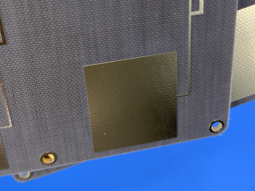
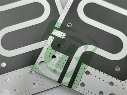
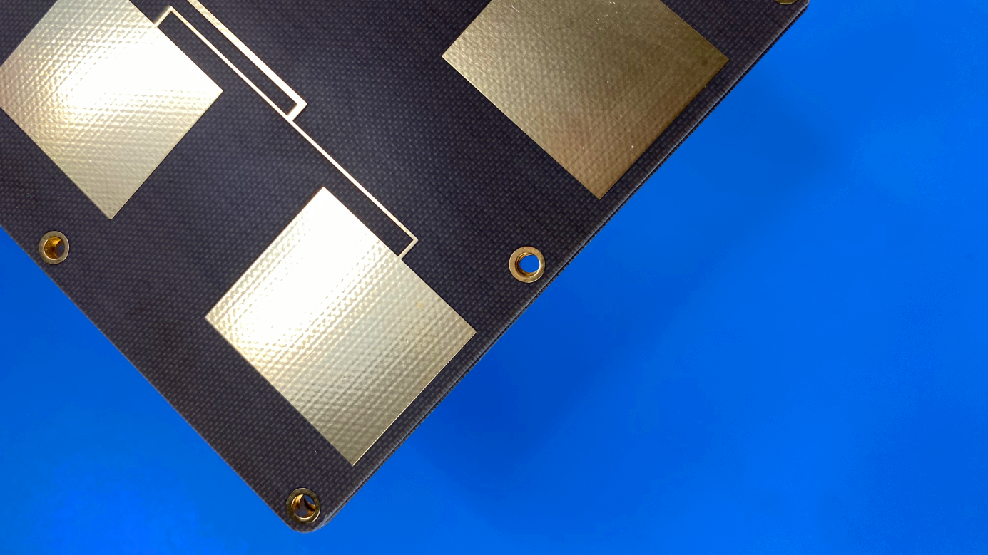
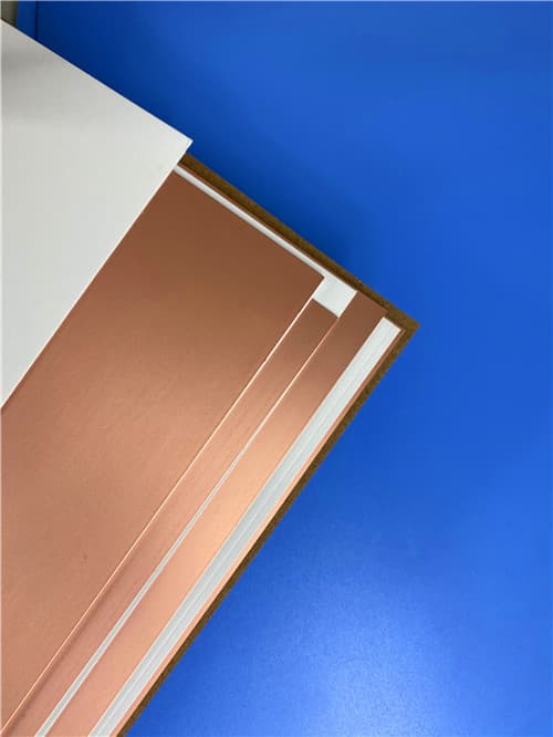
Taconic TLX-9 2-Layer 0.3mm EPIG (Nickel-Free) PCB – Low Dk RF Applications1. Introduction to Taconic TLX-9 PCB TLX-9 is a composite of PTFE/woven glass laminates with exceptionally well controlled electrical and mechanical properties. TLX-9 laminates can be sheared, drilled, milled and plated using standard methods for PTFE/woven fiberglass materials. The laminates are dimensionally stable, and exhibit virtually no moisture absorption during fabrication processes. TLX-9 measured 2.5 Dk with tightly controlled across a broad frequency range and temperature spectrum. The dissipation factor is approximately 0.0019 when measured at 10 GHz. TLX-9 meets stringent flammability standards, achieving a UL 94 V-0 certification for flame retardancy. This 2-layer rigid PCB is constructed entirely with Taconic TLX-9 as the core material, making it ideal for LNAs, LNBs, LNCs, PCS/PCN large format antennas, high power amplifiers, and passive components.
2. Key Features of Taconic TLX-9 PCB Dielectric constant of 2.5 at 10 GHz Dissipation factor of 0.0019 at 10 GHz Moisture absorption of <0.02% Dielectric breakdown of >60 kV Volume resistivity of 10⁷ Mohm/cm Surface resistivity of 10⁷ Mohm Arc resistance of >180 seconds Flexural strength lengthwise: >23,000 lbs/in (>159 N/mm²) Flexural strength crosswise: >19,000 lbs/in (>131 N/mm²) Peel strength (1 oz copper): 12 lbs/linear in (2.1 N/mm) Thermal conductivity of 0.19 W/(m·K) x-y CTE: 9-12 ppm/°C z CTE: 130-145 ppm/°C UL 94 V-0 flammability rating 3. Benefits of Taconic TLX-9 PCB Low dielectric constant Low dissipation factor Low moisture absorption High dielectric breakdown Good peel strength Controlled coefficient of thermal expansion (CTE) Dimensionally stable Exceptionally well controlled electrical and mechanical properties 4.Taconic TLX-9 PCB Construction Details
5. PCB Stackup (2-Layer Rigid Structure) Copper_layer_1 - 35 μm (1 oz) Taconic TLX-9 Core - 0.254 mm (10 mil) Copper_layer_2 - 35 μm (1 oz) 6. PCB Statistics Components: 29 Total Pads: 45 Thru Hole Pads: 24 Top SMT Pads: 21 Bottom SMT Pads: 0 Vias: 19 Nets: 2 7. Primary Application Areas LNAs, LNBs, and LNCs PCS/PCN large format antennas High power amplifiers Passive components Radar systems Phased array antennas Mobile communication systems Microwave test equipment Microwave transmission devices RF components 8.Quality Assurance Type of artwork supplied: Gerber RS-274-X Accepted standard: IPC-Class-3 Availability: Worldwide 9. Taconic TLX-9 PTFE/Woven Glass Laminate – Product Introduction Taconic has over 35 years of experience coating fiberglass fabric with PTFE (polytetrafluoroethylene). This enables Taconic to manufacture copper clad PTFE/woven glass laminates with exceptionally well controlled electrical and mechanical properties. The dielectric constant (Dk) range is 2.45 to 2.65. The Dk can be specified anywhere within this range with a tolerance of ±0.04. The dissipation factor is approximately 0.0019 when measured at 10 GHz. TLX laminates can be sheared, drilled, milled and plated using standard methods for PTFE/woven fiberglass materials. The laminates are dimensionally stable, and exhibit virtually no moisture absorption during fabrication processes. TLX laminates are generally ordered clad on one or both sides with 1/2, 1, or 2 oz. electrodeposited copper. Contact customer service for alternate claddings. TLX laminates are tested in accordance with IPC-TM 650. A Certificate of Compliance containing actual test data accompanies each shipment.
10. Features and Benefits Summary
11.Taconic TLX-9 Data Sheet
12. Some Typical Applications LNAs, LNBs, and LNCs PCS/PCN large format antennas High power amplifiers Passive components Radar systems Phased array antennas Mobile communication systems Microwave test equipment Microwave transmission devices RF components 13. Standard Thicknesses, Panel Sizes & Claddings TLX-9 Dielectric Thickness Options
Standard Panel Sizes
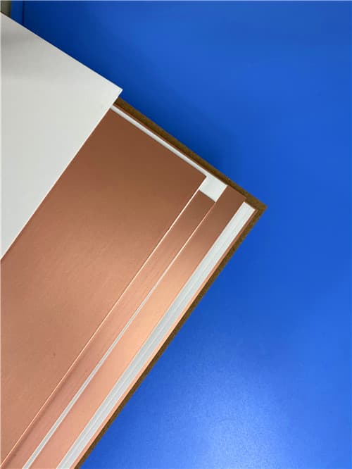
Standard Electrodeposited Copper Claddings
|
Get a Quick Quote
Fill in the form below and our engineers will reply within 24 hours with technical specifications and pricing for Taconic TLX-9 2-Layer 0.3mm EPIG (Nickel-Free) PCB.
.png)