| |
Rogers RT/duroid 5880 4-Layer Hybrid RF/FR-4 PCB with Immersion Silver
1.Introduction
RT/duroid 5880 is a glass microfiber reinforced PTFE composite designed for high-performance stripline and microstrip printed circuit board applications. With a dielectric constant of 2.20 and ultra-low dissipation factor, it provides exceptional electrical consistency and signal integrity, making it suitable for demanding RF and microwave systems up to Ku-band and beyond.
2.Key Features and Benefits
Low and Stable Dielectric Constant: Dk = 2.20 ±0.02 at 10 GHz, with excellent uniformity and frequency stability.
Ultra-Low Loss: Dissipation factor as low as 0.0009 at 10 GHz, supporting high-frequency, low-loss designs.
Excellent Thermal Stability: Thermal coefficient of εr = –125 ppm/°C, ensuring reliable performance across temperature ranges.
High Electrical Insulation: Volume resistivity ≥2×10⁷ MΩ·cm and surface resistivity ≥3×10⁷ MΩ.
Good Mechanical Properties: Balanced tensile and compressive modulus for reliable PCB fabrication and assembly.
Lead-Free Process Compatible: Yes.
Flammability Rating: UL94 V-0.
3.Typical Properties
| Property |
Direction |
Units |
Condition |
Value |
Test Method |
| Dielectric Constant, εr (Process) | Z | – | C24/23/50, 10 GHz | 2.20 ± 0.02 | IPC-TM-650 2.5.5.5 |
| Dielectric Constant, εr (Design) | Z | – | 8–40 GHz | 2.20 | Differential Phase Length Method |
| Dissipation Factor, tan δ | Z | – | C24/23/50, 10 GHz | 0.0009 | IPC-TM-650 2.5.5.5 |
| Thermal Coefficient of εr | Z | ppm/°C | –50°C to 150°C | –125 | IPC-TM-650 2.5.5.5 |
| Volume Resistivity | Z | MΩ·cm | C96/35/90 | 2×10⁷ | ASTM D257 |
| Surface Resistivity | Z | MΩ | C96/35/90 | 3×10⁷ | ASTM D257 |
| Tensile Modulus (X) | X | MPa (kpsi) | 23°C | 1070 (156) | ASTM D638 |
| Tensile Modulus (Y) | Y | MPa (kpsi) | 23°C | 860 (125) | ASTM D638 |
| Compressive Modulus (Z) | Z | MPa (kpsi) | 23°C | 940 (136) | ASTM D695 |
| Moisture Absorption | N/A | % | D48/50, 0.062" | 0.02 | ASTM D570 |
| Thermal Conductivity | Z | W/(m·K) | 80°C | 0.20 | ASTM C518 |
| CTE (X) | X | ppm/°C | 0–100°C | 31 | IPC-TM-650 2.4.41 |
| CTE (Y) | Y | ppm/°C | 0–100°C | 48 | IPC-TM-650 2.4.41 |
| CTE (Z) | Z | ppm/°C | 0–100°C | 237 | IPC-TM-650 2.4.41 |
| Density | N/A | g/cm³ | N/A | 2.2 | ASTM D792 |
| Copper Peel Strength | N/A | pli (N/mm) | 1 oz EDC after solder float | 31.2 (5.5) | IPC-TM-650 2.4.8 |

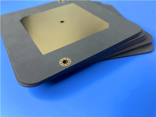
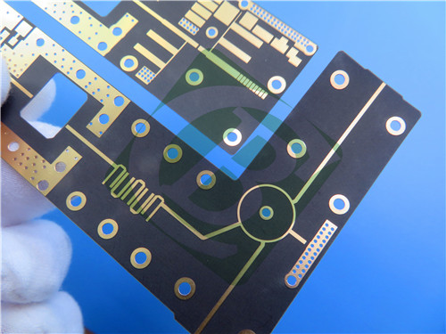
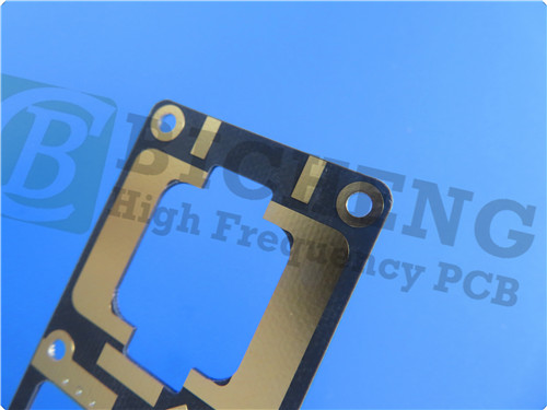
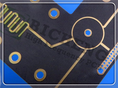
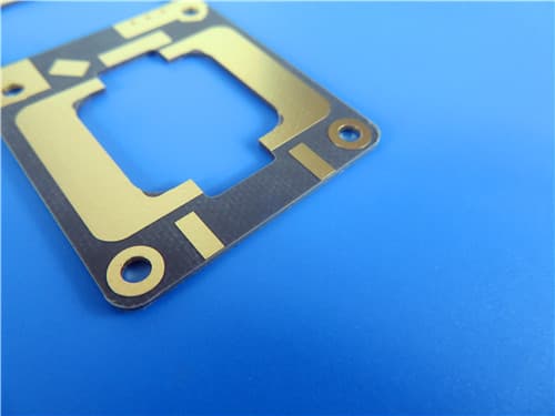
4.PCB Construction Details
| Specification |
Value |
| Layer Structure | 4-layer hybrid stackup: RT5880 + FR-4 prepreg + RT5880 |
| Outer Layers | 1 oz (35 µm) copper |
| Inner Layers | 0.5 oz (17.5 µm) copper |
| Board Dimensions | 126mm × 63mm (±0.15mm) |
| Minimum Trace/Space | 5/5 mils |
| Minimum Hole Size | 0.2mm |
| Via Pad Size | 0.5mm |
| Via Type | Through-hole only, no blind/buried vias |
| Finished Board Thickness | 0.833mm |
| Surface Finish | Immersion Silver |
| Solder Mask | Green, no silkscreen |
| Electrical Test | 100% prior to shipment |
5.PCB Stackup (4-Layer Rigid Structure)
Layer 1 (Top): RT5880 – 0.254mm
Prepreg: TG170 FR-4 – 0.204mm
Layer 2 & 3: Core – RT5880 – 0.254mm
Layer 4 (Bottom): RT5880 – 0.254mm
Total Finished Thickness: 0.833mm
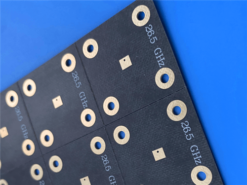
6.Typical Applications
RF & Microwave Circuits: Stripline and microstrip designs for communication systems
Ku-band and Above Applications: Satellite communications, radar systems
Aerospace & Defense: Avionics, phased array antennas, electronic warfare
Test & Measurement: High-frequency probes, calibration substrates
Medical Electronics: High-frequency imaging and diagnostic equipment
7.Quality Assurance
Artwork Format: Gerber RS-274-X
Quality Standard: IPC-Class-2
Availability: Worldwide
|
|
.jpg)
.jpg)