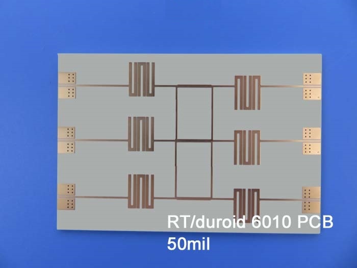
Rogers High Frequency PCB Built on RT/Duroid 6010 DK 10.2 50mil With Immersion Gold for Satellite Communications Systems
(Printed Circuit Boards are custom-made products; the images and specifications shown are for reference only.)
Hello Everyone,
Today, we will explore the features of the Rogers 6010 PCB.
Rogers RT/Duroid 6010LM microwave laminates are ceramic-PTFE composites specifically designed for high-performance electronic and microwave circuit applications requiring a high dielectric constant. This material is available with a dielectric constant value of 10.2, making it ideal for various applications.
PCB Capability (RT/Duroid 6010)
PCB Material |
Ceramic-PTFE composite |
Designator |
RT/Duroid 6010LM |
Dielectric Constant |
10.2 ±0.25 (process), 10.7 (design) |
Layer Count |
1 Layer, 2 Layer |
Copper Weight |
0.5oz (17 µm), 1oz (35µm), 2oz (70µm) |
PCB Thickness |
10mil (0.254mm), 25mil (0.635mm), 50mil (1.27mm), 75mil (1.90mm) |
PCB Size |
≤400mm x 500mm |
Solder Mask |
Green, Black, Blue, Yellow, Red, etc. |
Surface Finish |
Bare Copper, HASL, ENIG, Immersion Tin, Immersion Silver, OSP |
RT/Duroid 6010LM microwave laminates offer ease of fabrication and stability during use. These properties facilitate mass production and reduce overall costs. The material features tight dielectric constant and thickness control, low moisture absorption, and excellent thermal-mechanical stability.
Features and Benefits
1.High Dielectric Constant: Enables circuit size reduction.
2.Low Loss: Ideal for operation at X-band frequencies and below.
3.Moisture Resistance: Low moisture absorption minimizes electrical loss.
4.Z-Axis Stability: Provides reliable plated through-holes (PTH) in multilayer boards.
5.Tight DK and Thickness Control: Ensures repeatable circuit performance.
Typical Applications
Aircraft collision avoidance systems
Ground radar warning systems
Patch antennas
Satellite communications systems
Thank you for reading!
Appendix: Properties of RT/Duroid 6010LM laminates
RT/duroid 6010 Typical Value |
|||||
Property |
RT/duroid 6010 |
Direction |
Units |
Condition |
Test Method |
Dielectric Constant,εProcess |
10.2±0.25 |
Z |
|
10 GHz/23℃ |
IPC-TM-650 2.5.5.5 Clamped stripline |
Dielectric Constant,εDesign |
10.7 |
Z |
|
8GHz to 40 GHz |
Differential Phase Length Method |
Dissipation Factor,tanδ |
0.0023 |
Z |
|
10 GHz/A |
IPC-TM-650 2.5.5.5 |
Thermal Coefficient of ε |
-425 |
Z |
ppm/℃ |
-50℃-170℃ |
IPC-TM-650 2.5.5.5 |
Volume Resistivity |
5 x 10⁵ |
|
Mohm.cm |
A |
IPC 2.5.17.1 |
Surface Resistivity |
5 x 10⁶ |
|
Mohm |
A |
IPC 2.5.17.1 |
Tensile Properties |
ASTM D638 (0.1/min. strain rate) |
||||
Young's Modulus |
931(135) 559(81) |
X Y |
MPa(kpsi) |
A |
|
Ultimate Stress |
17(2.4) 13(1.9) |
X Y |
MPa(kpsi) |
A |
|
Ultimate Strain |
9 to 15 7 to 14 |
X Y |
% |
A |
|
Compressive Properties |
|
ASTM D695 (0.05/min. strain rate) |
|||
Young's Modulus |
2144 (311) |
Z |
MPa(kpsi) |
A |
|
Ultimate Stress |
47(6.9) |
Z |
MPa(kpsi) |
A |
|
Ultimate Strain |
25 |
Z |
% |
|
|
Flexural Modulus |
4364 (633) 3751 (544) |
X |
MPa(kpsi) |
A |
ASTM D790 |
Ultimate Stress |
36 (5.2) 32 (4.4) |
X Y |
MPa(kpsi) |
A |
|
Deformation under load |
0.26 1.3 |
Z Z |
% |
24hr/50℃/7MPa 24hr/150℃/7MPa |
ASTM D261 |
Moisture Absorption |
0.01 |
|
% |
D48/50℃ 0.050"(1.27mm) thick |
IPC-TM-650 2.6.2.1 |
Thermal Conductivity |
0.86 |
|
W/m/k |
80℃ |
ASTM C518 |
Coefficient of Thermal Expansion |
24 |
X |
ppm/℃ |
23℃/50% RH |
IPC-TM-650 2.4.41 |
Td |
500 |
|
℃ TGA |
|
ASTM D3850 |
Density |
3.1 |
|
g/cm3 |
|
ASTM D792 |
Specific Heat |
1.00(0.239) |
|
j/g/k |
|
Calculated |
Copper Peel |
12.3 (2.1) |
|
pli (N/mm) |
after solder float |
IPC-TM-650 2.4.8 |
Flammability |
V-0 |
|
|
|
UL 94 |
Lead-free Process Compatible |
Yes |
|
|
|
|