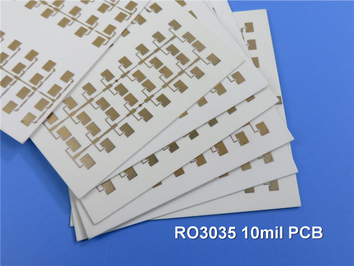
Rogers RO3035 High Frequency PCB 2-Layer Rogers 3035 10mil Circuit Board DK3.5 DF 0.0015 Microwave PCB
(Note: Printed Circuit Boards (PCBs) are custom-made products. The images and specifications provided are for reference only.)
Overview of Rogers RO3035 High Frequency Circuit Materials
The Rogers RO3035 high frequency PCB is crafted from ceramic-filled PTFE composites, specifically designed for commercial microwave and RF applications. This material delivers exceptional electrical and mechanical stability at competitive prices. Its consistent mechanical properties enable designers to create multi-layer board configurations without issues such as warpage or reliability concerns.
The RO3035 materials have a coefficient of thermal expansion (CTE) of 17 ppm/℃ in both the X and Y axes, which closely matches that of copper. This compatibility ensures excellent dimensional stability, with typical etch shrinkage post-processing of less than 0.5 mils per inch. The Z-axis CTE is 24 ppm/℃, providing outstanding reliability for plated through-holes, even in demanding environments.
Typical Applications
- 1.Automotive radar systems
- 2.Cellular telecommunications networks
- 3.Datalink over cable systems
- 4.Direct broadcast satellite technology
- 5.Global Positioning System (GPS) antennas
- 6.Patch antennas for wireless communication
- 7.Power amplifiers and antennas
- 8.Power backplanes
- 9.Remote meter reading devices
.jpg)
PCB Specifications
Rogers RO3035 10mil 0.254mm High Frequency PCB DK3.5 RF PCB for Patch Antenna for Wireless Communications |
||
PCB SIZE |
55 x 57mm=1PCS |
|
BOARD TYPE |
Double sided PCB |
|
Number of Layers |
2 layers |
|
Surface Mount Components |
YES |
|
Through Hole Components |
YES |
|
LAYER STACKUP |
copper ------- 18um(0.5 oz)+plate TOP layer |
|
RO3035 0.254mm |
||
copper ------- 18um(0.5 oz) + plate BOT Layer |
||
TECHNOLOGY |
|
|
Minimum Trace and Space: |
4 mil / 4 mil |
|
Minimum / Maximum Holes: |
0.4 mm / 5.5 mm |
|
Number of Different Holes: |
5 |
|
Number of Drill Holes: |
79 |
|
Number of Milled Slots: |
0 |
|
Number of Internal Cutouts: |
0 |
|
Impedance Control: |
no |
|
Number of Gold finger: |
0 |
|
BOARD MATERIAL |
|
|
Glass Epoxy: |
RO3035 0.254mm |
|
Final foil external: |
1 oz |
|
Final foil internal: |
N/A |
|
Final height of PCB: |
0.3 mm ±0.1 |
|
PLATING AND COATING |
|
|
Surface Finish |
Immersion gold |
|
Solder Mask Apply To: |
N/A |
|
Solder Mask Color: |
N/A |
|
Solder Mask Type: |
N/A |
|
CONTOUR/CUTTING |
Routing |
|
MARKING |
|
|
Side of Component Legend |
N/A |
|
Colour of Component Legend |
N/A |
|
Manufacturer Name or Logo: |
N/A |
|
VIA |
Plated through hole(PTH), minimum size 0.4mm. |
|
FLAMIBILITY RATING |
UL 94-V0 Approval MIN. |
|
DIMENSION TOLERANCE |
|
|
Outline dimension: |
0.0059" |
|
Board plating: |
0.0029" |
|
Drill tolerance: |
0.002" |
|
TEST |
100% Electrical Test prior shipment |
|
TYPE OF ARTWORK TO BE SUPPLIED |
email file, Gerber RS-274-X, PCBDOC etc |
|
SERVICE AREA |
Worldwide, Globally. |
|
PCB Capability (RO3035)
PCB Material: |
Ceramic-filled PTFE Composites |
Designation: |
RO3035 |
Dielectric constant: |
3.5 |
Dissipation Factor |
0.0015 10GHz |
Layer count: |
Single Sided PCB, Double Sided PCB, Multilayer PCB, Hybrid PCB |
Copper weight: |
1oz (35µm), 2oz (70µm) |
Laminate thickness: |
5mil(0.127mm), 10mil(0.254mm), 20mil(0.508mm), 30mil (0.762mm), 60mil (1.524mm ) |
PCB size: |
≤400mm X 500mm |
Solder mask: |
Green, Black, Blue, Yellow, Red etc. |
Surface finish: |
Bare copper, HASL, ENIG, Immersion silver, Immersion tin, ENEPIG, OSP, Pure gold plated etc.. |
Data Sheet for Rogers 3035 (RO3035)
RO3035 Typical Value |
|||||
Property |
RO3035 |
Direction |
Units |
Condition |
Test Method |
Electrical Properties |
|
|
|
|
|
Dielectric Constant,εProcess |
3.50±0.05 |
Z |
|
10 GHz/23℃ |
IPC-TM-650 2.5.5.5 Clamped Stripline |
Dielectric Constant,εDesign |
3.6 |
Z |
|
8GHz to 40 GHz |
Differential Phase Length Method |
Dissipation Factor,tanδ |
0.0015 |
Z |
|
10 GHz/23℃ |
IPC-TM-650 2.5.5.5 |
Thermal Coefficient of ε |
-45 |
Z |
ppm/℃ |
10 GHz -50℃to 150℃ |
IPC-TM-650 2.5.5.5 |
Volume Resistivity |
107 |
|
MΩ.cm |
COND A |
IPC 2.5.17.1 |
Surface Resistivity |
107 |
|
MΩ |
COND A |
IPC 2.5.17.1 |
Thermal Properties |
|
|
|
|
|
Td |
500 |
|
℃ TGA |
|
ASTM D 3850 |
Coefficient of Thermal Expansion |
17 |
X |
ppm/℃ |
23℃/50% RH |
IPC-TM-650 2.4.4.1 |
Thermal Conductivity |
0.5 |
|
W/M/K |
50℃ |
ASTM D 5470 |
Mechanical Properties |
|
|
|
|
|
Copper Peel Stength |
10.2 |
|
Ib/in. |
1oz,EDC After Solder Float |
IPC-TM 2.4.8 |
Young's Modulus |
1025 |
|
MPa |
23℃ |
ASTM D 638 |
Dimensional Stability (MD, CMD) |
-0.11 0.11 |
|
mm/m |
Condition A |
IPC TM-650 2.2.4 |
Physical Properties |
|
|
|
|
|
Flammability |
V-0 |
|
|
|
UL 94 |
Moisture Absorption |
0.04 |
|
% |
D48/50 |
IPC-TM-650 2.6.2.1 |
Density |
2.1 |
|
gm/cm3 |
23℃ |
ASTM D 792 |
Lead-free Process Compatible |
Yes |
|
|
|
|