Rogers RO3210 High Frequency PCB with 25mil and 50mil Coating Immersion Gold, Immersion Tin and Immersion Silver
(PCBs are custom-made products; the images and specifications provided are for reference only.)
Hello Everyone,
Today, we will discuss the RO3210 high frequency PCBs.
RO3210 high frequency circuit laminates are ceramic-filled materials reinforced with woven fiberglass. This material is an extension of the RO3000 series, featuring one key advantage—enhanced mechanical stability.
Features and Applications
Key Features:
1.Woven Glass Reinforcement: Provides improved rigidity for easier handling.
2.Consistent Electrical and Mechanical Performance: Ideal for complex multi-layer high frequency structures.
3.Low In-Plane Expansion Coefficient: Matches that of copper, ensuring reliability for surface-mounted assemblies and suitability for epoxy multi-layer board hybrid designs.
4.Excellent Dimensional Stability: Leads to high production yields.
5.Smooth Surface Finish: Allows for fine line etching tolerances.
Our PCB Capabilities (RO3210):
PCB Capability (RO3210) |
|
PCB Material: |
Ceramic-filled Laminates Reinforced with Woven Fiberglass |
Designation: |
RO3210 |
Dielectric constant: |
10.2±0.5 |
Layer count: |
Single Layer, Double Layer, Multilayer, Hybrid PCB |
Copper weight: |
1oz (35µm), 2oz (70µm) |
Typical Applications:
1.Automotive Collision Avoidance Systems
2.Automotive Global Positioning Satellite Antennas
3.Base Station Infrastructure
4.Datalink on Cable Systems
5.Direct Broadcast Satellite
6.LMDS and Wireless Broadband
7.Microstrip Patch Antennas for Wireless Communications
8.Power Backplanes
9.Remote Meter Readers
10.Wireless Telecommunications Systems
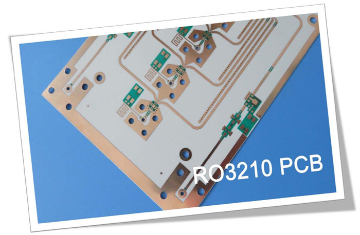
The standard color of the RO3210 PCB is white. The manufacturing process for the RO3210 high frequency PCB is similar to that of standard PTFE PCBs, making it suitable for high-volume manufacturing and providing a competitive advantage in the market.
If you have any questions, please feel free to contact us.
Thank you for reading.
Appendix: Data Sheet of RO3210
Property |
Typical Value RO3210 |
Direction |
Unit |
Condition |
Test Method |
Dielectric Constant, er Process |
10.2± 0.50 |
Z |
- |
10 GHz 23°C |
IPC-TM-650 2.5.5.5 |
Dielectric Constant, er Design |
10.8 |
Z |
- |
8 GHz - 40 GHz |
Differential Phase Length Method |
Dissipation Factor, tan d |
0.0027 |
Z |
- |
10 GHz 23°C |
IPC-TM-650 2.5.5.5 |
Thermal Coefficient of er |
-459 |
Z |
ppm/°C |
10 GHz 0-100°C |
IPC-TM-650 2.5.5.5 |
Dimensional Stability |
0.8 |
X,Y |
mm/m |
COND A |
ASTM D257 |
Volume Resistivity |
103 |
|
MW•cm |
COND A |
IPC 2.5.17.1 |
Surface Resistivity |
103 |
|
MW |
COND A |
IPC 2.5.17.1 |
Tensile Modulus |
579 |
MD CMD |
kpsi |
23°C |
ASTM D638 |
Water Absorption |
<0.1 |
- |
% |
D24/23 |
IPC-TM-650 2.6.2.1 |
Specific Heat |
0.79 |
|
J/g/K |
|
Calculated |
Thermal Conductivity |
0.81 |
- |
W/m/K |
80°C |
ASTM C518 |
Coefficient of Thermal Expansion (-55 to 288 °C) |
13 |
X,Y, Z |
ppm/°C |
23°C/50% RH |
IPC-TM-650 2.4.41 |
Td |
500 |
|
°C |
TGA |
ASTM D3850 |
Color |
Off White |
|
|
|
|
Density |
3.0 |
|
gm/cm3 |
|
|
Copper Peel Strength |
11.0 |
|
pli |
1 oz. EDC |
IPC-TM-2.4.8 |
Flammability |
V-0 |
|
|
|
UL 94 |
Lead Free Process Compatible |
YES |
|
|
|
|