Taconic RF-35TC High Frequency PCB 60mil 1.525mm Double-Sided RF PCB with Immersion Gold
(Note: PCBs are custom-made products; images and specifications provided are for reference only.)
Introduction
Welcome to our overview of the Taconic RF-35TC high frequency PCB, a cutting-edge solution designed for advanced applications.
RF-35TC Overview
The RF-35TC material is a PTFE-based, ceramic-filled fiberglass high frequency substrate from Taconic. This material is engineered for optimal performance in high-power applications.
.jpg)
PCB Specifications
Specification |
Details |
Layer Count |
Double-sided |
Base Material |
RF-35TC, DK 3.5 |
Dimensions |
105 mm x 87 mm |
Finished Thickness |
1.6 mm ±10% |
Finished Copper Weight |
2 oz |
Solder Mask |
No |
Surface Finish |
Immersion Gold |
Detailed Description
Our double-sided PCB features an RF-35TC substrate with a dielectric constant (DK) of 3.5. The dimensions are 105 mm in length and 87 mm in width, with a final thickness of 1.6 mm and a copper weight of 2 oz. This PCB does not include a solder mask or silkscreen, and the surface finish is Immersion Gold.
Stack-Up Drawing
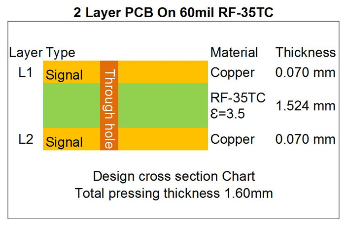
- *Top Layer: 2 oz finished copper
- *Bottom Layer: 2 oz finished copper
- *Dielectric Material: RF-35TC, 1.524 mm thick, DK 3.5
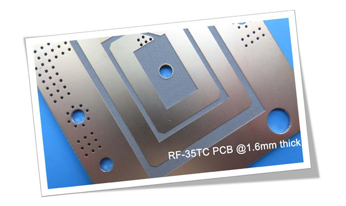
Color and Applications
The standard color of the RF-35TC PCB is brown and grey. This PCB is ideal for a variety of applications, including:
- Power Amplifiers
- Couplers
- Filters
- Antennas
- Satellite Equipment
Our PCB Capabilities (RF-35TC)
Capability |
Details |
PCB Material |
PTFE-based ceramic-filled fiberglass |
Designator |
RF-35TC |
Dielectric Constant @ 10GHz |
3.50 |
Layer Count |
2 Layer, Multilayer, Hybrid Type |
Copper Weight |
0.5 oz, 1 oz, 2 oz |
PCB Thickness |
0.3 mm, 0.6 mm, 0.8 mm, 1.6 mm (10 mil, 20 mil, 30 mil, 60 mil substrate) |
Solder Mask |
Available in Green, Red, Black, White, Blue, etc. |
PCB Size |
≤ 400 mm x 500 mm |
Surface Finish |
Bare copper, HASL, ENIG, Immersion Tin, etc. |
Conclusion
We specialize in providing double-sided, multilayer, and hybrid PCBs. Our thickness options range from 0.3 mm to 1.6 mm, with a maximum size of 400 mm by 500 mm. Surface finishes include bare copper, hot air level, and immersion gold.
The RF-35TC material offers exceptional heat dissipation performance, making it suitable for high-power applications. It efficiently dissipates heat from both the transmission lines and surface mount components, ensuring reliable operation.
For any inquiries, please feel free to reach out!
Thank you for reading.
Appendix:Data Sheet RF-35TC
RF-35TC TYPICAL VALUES |
|||||
Property |
Test Method |
Unit |
Value |
Unit |
Value |
DK @10 GHz |
IPC-650 2.5.5.5.1(modified) |
|
3.5 |
|
3.5 |
Tck(-30 to 120℃) |
IPC-650 2.5.5.5.1(modified) |
ppm |
24 |
ppm |
24 |
Df @10 GHz |
IPC-650 2.5.5.5.1(modified) |
|
0.0011 |
|
0.0011 |
Dielectric Breakdown |
IPC-650 2.5.6(in-Plane,Two Pins in Oil) |
kV |
56.7 |
kV |
56.7 |
Dielectric Strength |
ASTM D 149(Through Plane) |
V/mil |
570 |
V/mm |
22,441 |
Arc Resistance |
IPC-650 2.5.1 |
Seconds |
304 |
Seconds |
304 |
Moisture Absorption |
IPC-650 2.6.2.1 |
% |
0.05 |
% |
0.05 |
Flexural Strength(MD) |
ASTM D 790/IPC-650 2.4.4 |
psi |
12,900 |
N/mm2 |
88.94 |
Flexural Strength(CD) |
ASTM D 790/IPC-650 2.4.4 |
psi |
11,700 |
N/mm2 |
80.67 |
Tensile Strength(MD) |
ASTM D 3039/IPC-TM-650 2.4.19 |
psi |
9,020 |
N/mm2 |
62.19 |
Tensile Strength(CD) |
ASTM D 3039/IPC-TM-650 2.4.19 |
psi |
7,740 |
N/mm2 |
53.37 |
Elongation at Break(MD) |
ASTM D 3039/IPC-TM-650 2.4.19 |
% |
1.89 |
N/mm |
1.89 |
Elongation at Break(CD) |
ASTM D 3039/IPC-TM-650 2.4.19 |
% |
1.7 |
% |
1.7 |
Young's Modulus(MD) |
ASTM D 3039/IPC-TM-650 2.4.19 |
psi |
667,000 |
N/mm2 |
4,599 |
Young's Modulus(CD) |
ASTM D 3039/IPC-TM-650 2.4.19 |
psi |
637,000 |
N/mm2 |
4,392 |
Poisson's Ratio(MD) |
ASTM D 3039/IPC-TM-650 2.4.19 |
|
0.18 |
|
0.18 |
Poisson's Ratio(CD) |
ASTM D 3039/IPC-TM-650 2.4.19 |
|
0.23 |
|
0.18 |
Compressive Modulus |
ASTM D 695(23℃) |
psi |
560,000 |
N/mm2 |
3,861 |
Flexural Strength(MD) |
ASTM D 790/IPC-650 2.4.4 |
psi |
1.46 x 10⁶ |
N/mm2 |
10,309 |
Flexural Strength(CD) |
ASTM D 790/IPC-650 2.4.4 |
psi |
1.50 x 10⁶ |
N/mm2 |
10,076 |
Peel Stength(½ oz.CVH) |
IPC-650 2.4.8(Thermal Stress.) |
Ibs./inch |
7 |
g/cm3 |
1.25 |
Thermal Conductivity(Unclad,125℃) |
ASTM F433(Guarded Heat Flow) |
W/(mK) |
0.6 |
W/(mK) |
0.6 |
Thermal Conductivity(C1/C1,125℃) |
ASTM F433(Guarded Heat Flow) |
W/(mK) |
0.92 |
W/(mK) |
0.92 |
Thermal Conductivity(CH/CH,125℃) |
ASTM F433(Guarded Heat Flow) |
W/(mK) |
0.87 |
W/(mK) |
0.87 |
Dimensional Stability(MD) |
IPC-650-2.4.39 Sec.5.4(After Etch) |
mils/in. |
0.23 |
mm/M |
0.23 |
Dimensional Stability(CD) |
IPC-650-2.4.39 Sec.5.4(After Etch) |
mils/in. |
0.64 |
mm/M |
0.64 |
Dimensional Stability(MD) |
IPC-650-2.4.39 Sec.5.5(Thermal Stress.) |
mils/in. |
-0.04 |
mm/M |
-0.04 |
Dimensional Stability(CD) |
IPC-650-2.4.39 Sec.5.5(Thermal Stress.) |
mils/in. |
0.46 |
mm/M |
0.46 |
Surface Resistivity |
IPC-650 2.5.17.1(after elevated temp.) |
Mohms |
8.33 x 10⁷ |
Mohms |
8.33 x 10⁷ |
Surface Resistivity |
IPC-650 2.5.17.1(after humidity) |
Mohms |
6.42 x 10⁷ |
Mohms |
6.42 x 10⁷ |
Volume Resistivity |
IPC-650 2.5.17.1(after elevated temp.) |
Mohms/cm |
5.19 x 10⁸ |
Mohms/cm |
5.19 x 10⁸ |
Volume Resistivity |
IPC-650 2.5.17.1(after humidity) |
Mohms/cm |
2.91 x 10⁸ |
Mohms/cm |
2.91 x 10⁸ |
CTE(X axis)(25-260℃) |
IPC-650 2.4.41/ASTM D 3386 |
ppm/℃ |
11 |
ppm/℃ |
11 |
CTE(Y axis)(25-260℃) |
IPC-650 2.4.41/ASTM D 3386 |
ppm/℃ |
13 |
ppm/℃ |
13 |
CTE(Z axis)(25-260℃) |
IPC-650 2.4.41/ASTM D 3386 |
ppm/℃ |
34 |
ppm/℃ |
34 |
Density |
ASTM D 792 |
g/cm3 |
2.35 |
g/cm3 |
2.35 |
Hardness |
ASTM D 2240(Shore D) |
|
79.1 |
|
79.1 |
Strain at Break(MD) |
ASTM D 790/IPC-650 2.4.4 |
% |
0.014 |
% |
0.014 |
Strain at Break(CD) |
ASTM D 790/IPC-650 2.4.4 |
% |
0.013 |
% |
0.013 |
Specific Heat |
ASTM E 1269-05,E 967-08,E968-02 |
j/(g℃) |
0.94 |
j/(g℃) |
0.94 |
Td(2% Weight Loss) |
IPC-650 2.4.24.6/TGA |
oF |
788 |
℃ |
420 |
Td(5% Weight Loss) |
IPC-650 2.4.24.6/TGA |
oF |
817 |
℃ |
436 |