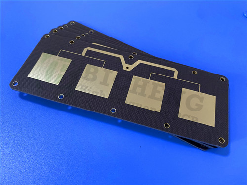
Taconic TLX-8 High Frequency PCB 62mil (1.575mm) RF Circuit Board with OSP
(Printed Circuit Boards are custom-made products; the images and parameters shown are for reference only.)
Introduction
The Taconic TLX-8 PCB is designed for reliability across a broad spectrum of RF applications. This versatile material features a dielectric constant (DK) range of 2.45 to 2.65, available in various thicknesses and copper cladding options. It is particularly suitable for low layer count microwave designs.
Material Overview
The TLX-8 PCB is constructed from PTFE-based fiberglass laminate, making it ideal for radar systems,mobile communications,microwave test equipment,microwave transmission devices,RF components.
Performance Features
TLX-8 serves as a robust solution in the RF microwave substrate market. Its fiberglass provides essential mechanical reinforcement in extreme environments, including:
- High vibration resistance for PCBs mounted in housings during space launches
- High-temperature exposure in engine modules
- Radiation resistance for space applications
- Antennas for naval vessels facing harsh maritime conditions
- Substrates for altimeters that operate under varying temperatures during flight
TLX Family Overview
The TLX family includes various options:
- TLX-0 (DK 2.45)
- TLX-9 (DK 2.50)
- TLX-8 (DK 2.55)
- TLX-7 (DK 2.60)
- TLX-6 (DK 2.65)
Dielectric thicknesses are as follows:
The TLX family includes several variants:
- TLX-0 (DK 2.45)
- TLX-9 (DK 2.50)
- TLX-8 (DK 2.55)
- TLX-7 (DK 2.60)
- TLX-6 (DK 2.65)
Dielectric thicknesses are as follows:
- TLX-0: 0.127mm to 6.35mm (5mil - 250mil)
- TLX-9: 0.05mm to 6.35mm (2mil - 250mil)
- TLX-8: 0.064mm to 6.35mm (2.5mil - 250mil)
- TLX-7: 0.089mm to 6.35mm (3.5mil - 250mil)
- TLX-6: 0.089mm to 6.35mm (3.5mil - 250mil)
Benefits of TLX-8 PCB
- Excellent Mechanical and Thermal Properties: Ensures durability and reliability.
- Low and Stable DK: Provides consistent performance.
- Dimensionally Stable: Maintains integrity under varying conditions.
- Low Moisture Absorption: Enhances longevity and reliability.
- UL 94 V-O Rating: Meets stringent safety standards.
- Tightly Controlled DK: Delivers precise performance in RF applications.
- Low DF: Minimizes signal loss for efficient operation.
Applications
The TLX-8 PCB is ideal for:
- Antennas
- Couplers
- Splitters
- Combiners
- Amplifiers
- Mixers
- Filters
- Passive components
PCB Specifications
Taconic TLX-8 62mil 1.575mm RF Antenna PCB TLT-8 High Frequency PCB for Directional Coupler |
|
PCB SIZE |
99 x 88mm=1PCS |
BOARD TYPE |
Double sided PCB |
Number of Layers |
2 layers |
Surface Mount Components |
YES |
Through Hole Components |
NO |
LAYER STACKUP |
copper ------- 35um(1 oz)+plate TOP layer |
TLX-8 1.575mm |
|
copper ------- 35um(1oz) + plate BOT Layer |
|
TECHNOLOGY |
|
Minimum Trace and Space: |
15 mil / 10 mil |
Minimum / Maximum Holes: |
0.5mm/2.0mm |
Number of Different Holes: |
N/A |
Number of Drill Holes: |
N/A |
Number of Milled Slots: |
0 |
Number of Internal Cutouts: |
0 |
Impedance Control: |
no |
Number of Gold finger: |
0 |
BOARD MATERIAL |
|
Glass Epoxy: |
TLX-8 1.575mm |
Final foil external: |
1 oz |
Final foil internal: |
N/A |
Final height of PCB: |
1.6 mm ±10% |
PLATING AND COATING |
|
Surface Finish |
OSP |
Solder Mask Apply To: |
N/A |
Solder Mask Color: |
N/A |
Solder Mask Type: |
N/A |
CONTOUR/CUTTING |
Routing |
MARKING |
|
Side of Component Legend |
N/A |
Colour of Component Legend |
N/A |
Manufacturer Name or Logo: |
N/A |
VIA |
N/A |
FLAMIBILITY RATING |
UL 94-V0 Approval MIN. |
DIMENSION TOLERANCE |
|
Outline dimension: |
0.0059" |
Board plating: |
0.0029" |
Drill tolerance: |
0.002" |
TEST |
100% Electrical Test prior shipment |
TYPE OF ARTWORK TO BE SUPPLIED |
email file, Gerber RS-274-X, PCBDOC etc |
SERVICE AREA |
Worldwide, Globally. |
TLX-8 Typical Value
TLX-8 TYPICAL VALUES |
|||||
Property |
Test Method |
Unit |
Value |
Unit |
Value |
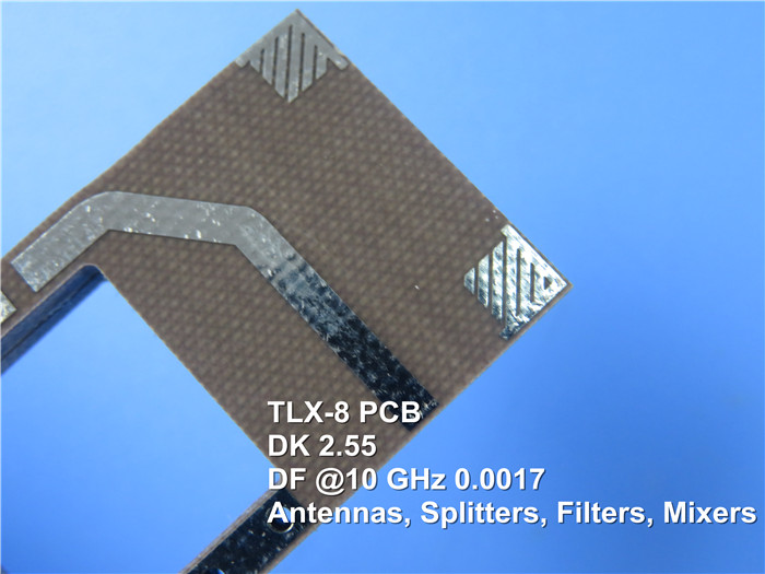
DK @10 GHz |
IPC-650 2.5.5.3 |
|
2.55 |
|
2.55 |
Df @1.9 GHz |
IPC-650 2.5.5.5.1 |
|
0.0012 |
|
0.0012 |
Df @10 GHz |
IPC-650 2.5.5.5.1 |
|
0.0017 |
|
0.0017 |
Dielectric Breakdown |
IPC-650 2.5.6 |
kV |
>45 |
kV |
>45 |
Moisture Absorption |
IPC-650 2.6.2.1 |
% |
0.02 |
% |
0.02 |
Flexural Strength(MD) |
ASTM D 709 |
psi |
28,900 |
N/mm2 |
|
Flexural Strength(CD) |
ASTM D 709 |
psi |
20,600 |
N/mm2 |
|
Tensile Strength(MD) |
ASTM D 902 |
psi |
35,600 |
N/mm2 |
|
Tensile Strength(CD) |
ASTM D 902 |
psi |
27,500 |
N/mm2 |
|
Elongation at Break(MD) |
ASTM D 902 |
% |
3.94 |
% |
3.94 |
Elongation at Break(CD) |
ASTM D 902 |
% |
3.92 |
% |
3.92 |
Young's Modulus(MD) |
ASTM D 902 |
kpsi |
980 |
N/mm2 |
|
Young's Modulus(CD) |
ASTM D 902 |
kpsi |
1,200 |
N/mm2 |
|
Young's Modulus(MD) |
ASTM D 3039 |
kpsi |
1,630 |
N/mm2 |
|
Poisson's Ratio |
ASTM D 3039 |
|
0.135 |
N/mm |
|
Peel Stength(1 oz.ed) |
IPC-650 2.4.8 Sec.5.2.2(Thermal Stress.) |
Ibs./linear inch |
15 |
N/mm |
|
Peel Stength(1 oz.RTF) |
IPC-650 2.4.8 Sec.5.2.2(Thermal Stress.) |
Ibs./linear inch |
17 |
N/mm |
|
Peel Stength(½ oz.ed) |
IPC-650 2.4.8.3(Elevated Temp.) |
Ibs./linear inch |
14 |
N/mm |
|
Peel Stength(½ oz.ed) |
IPC-650 2.4.8 Sec.5.2.2(Thermal Stress.) |
Ibs./linear inch |
11 |
N/mm |
|
Peel Stength(1 oz.rolled) |
IPC-650 2.4.8 Sec.5.2.2(Thermal Stress.) |
Ibs./linear inch |
13 |
N/mm |
2.1 |
Thermal Conductivity |
ASTM F433/ASTM 1530-06 |
W/M*K |
0.19 |
W/M*K |
0.19 |
Dimensional Stability(MD) |
IPC-650 2.4.39 Sec.5.5(After Bake.) |
mils/in. |
0.06 |
mm/M |
|
Dimensional Stability(CD) |
IPC-650 2.4.39 Sec.5.4(After Bake.) |
mils/in. |
0.08 |
mm/M |
|
Dimensional Stability(MD) |
IPC-650 2.4.39 Sec.5.5(Thermal Stress.) |
mils/in. |
0.09 |
mm/M |
|
Dimensional Stability(CD) |
IPC-650 2.4.39 Sec.5.5(Thermal Stress.) |
mils/in. |
0.1 |
mm/M |
|
Surface Resistivity |
IPC-650 2.5.17.1 Sec.5.2.1(Elevated Temp.) |
Mohm |
6.605 x 10⁸ |
Mohm |
6.605 x 10⁸ |
Surface Resistivity |
IPC-650 2.5.17.1 Sec.5.2.1(Humidity Cond.) |
Mohm |
3.550 x 10⁶ |
Mohm |
3.550 x 10⁶ |
Volume Resistivity |
IPC-650 2.5.17.1 Sec.5.2.1(Elevated Temp.) |
Mohm/cm |
1.110 x 10¹⁰ |
Mohm/cm |
1.110 x 10¹⁰ |
Volume Resistivity |
IPC-650 2.5.17.1 Sec.5.2.1(Humidity Cond.) |
Mohm/cm |
1.046 x 10¹⁰ |
Mohm/cm |
1.046 x 10¹⁰ |
CTE(X axis)(25-260℃) |
IPC-650 2.4.41/ASTM D 3386 |
ppm/℃ |
21 |
ppm/℃ |
21 |
CTE(Y axis)(25-260℃) |
IPC-650 2.4.41/ASTM D 3386 |
ppm/℃ |
23 |
ppm/℃ |
23 |
CTE(Z axis)(25-260℃) |
IPC-650 2.4.41/ASTM D 3386 |
ppm/℃ |
215 |
ppm/℃ |
215 |
Density(Specific Gravity) |
ASTM D 792 |
g/cm3 |
2.25 |
g/cm3 |
2.25 |
Td(2% Weight Loss) |
IPC-650 2.4.24.6(TGA) |
℃ |
535 |
℃ |
|
Td(5% Weight Loss) |
IPC-650 2.4.24.6(TGA) |
℃ |
553 |
℃ |
|
Flammability Rating |
UL-94 |
|
V-0 |
|
V-0 |