How Can RO3010+FR-4 Hybrid 4-Layer PCB Make Microwave, Radar, and Phased Array Circuits Smaller and More Stable?
 September 21, 2026
In commercial microwave, RF, radar, and phased array applications, PCBs often have to withstand high-frequency loss while also meeting challenges related to high density, heat dissipation, and long-term reliability. The RO3010 + FR-4 hybrid 4-layer board is a cost-effective solution designed for exactly these needs: it uses Rogers RO3010 ceramic-filled PTFE material as the core dielectric, bonding two 1.27mm RO3010 cores together with a single sheet of 1080 FR-4 prepreg in a symmetrical 4-layer hybrid structure. The finished board is approximately 2.8mm thick, with 1oz copper on all four layers and an immersion tin surface finish.
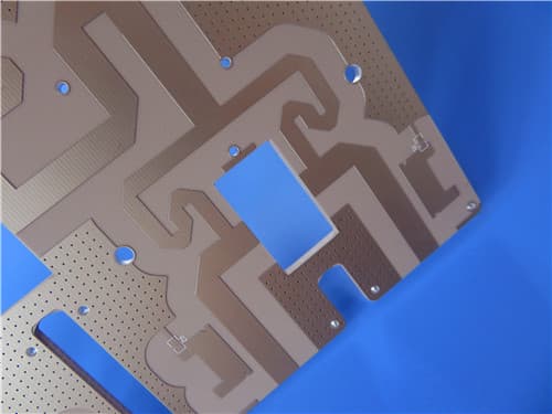
1. Material Selection: RO3010 and 1080 FR-4 Prepreg
RO3010 is a ceramic-filled PTFE composite laminate with a dielectric constant (Dk) of 10.2 ± 0.30 at 10GHz and a dissipation factor (Df) of only 0.0022. Its thermal coefficient of dielectric constant is -395 ppm/°C, thermal conductivity is 0.95 W/m/K, decomposition temperature (Td) is as high as 500°C, moisture absorption is only 0.05%, and it is compatible with lead-free processes with a UL 94 V-0 flammability rating. These characteristics allow it to maintain stable electrical performance at high frequencies while also providing good heat dissipation and dimensional stability.
The 1080 FR-4 prepreg is the key bonding layer in this hybrid structure. Its nominal thickness is only 0.076mm, and its resin content is relatively low, with a resin flow of approximately 10%–15%. The reason for choosing 1080 rather than thicker prepregs such as 2116 or 7628 is to minimize the volume proportion of FR-4 in the overall stackup while ensuring bonding strength, thereby reducing the impact of CTE mismatch between RO3010 and FR-4 and keeping the total thickness more controllable.
2. Stackup Design: Symmetry Is Key
The layer sequence of this 4-layer board is:
L1: Copper, 35μm (1oz)
Dielectric: RO3010 core, 1.27mm, Dk 10.2 ± 0.30 @ 10GHz
L2: Copper, 35μm (1oz)
Prepreg: 1080 FR-4 PP, 0.076mm
L3: Copper, 35μm (1oz)
Dielectric: RO3010 core, 1.27mm, Dk 10.2 ± 0.30 @ 10GHz
L4: Copper, 35μm (1oz)

The total dielectric thickness is 1.27 + 0.076 + 1.27 = 2.616mm. Adding four layers of 1oz copper (4 × 0.035mm = 0.14mm), the nominal finished thickness is approximately 2.756mm, which is rounded to 2.8mm in the specification.
This symmetrical 1.27 + 0.076 + 1.27mm structure is the core design for controlling warpage. The neutral axis is located at the center of the 1080 prepreg, and the RO3010 cores on both sides are identical in thickness and material properties. Therefore, thermal expansion is balanced on both sides of the center, effectively preventing the board from bowing or twisting during thermal cycling. At the same time, the 1080 prepreg is very thin, further reducing the volume of CTE mismatch caused by FR-4.
3. Manufacturing Process: The Challenges Lie in Bonding, Fill, and Warpage Control
The hybrid lamination of RO3010 and FR-4 presents three main process challenges:
First, PTFE surface bonding. The surface energy of RO3010 is very low, so surface treatment such as sodium etching is required to allow the 1080 prepreg to achieve sufficient peel strength. Otherwise, even if the stackup design is reasonable, delamination may occur during subsequent thermal cycling.
Second, resin flow and fill. The 1080 prepreg has low resin content and low flow, so when facing thicker inner-layer copper or large etched areas, it is prone to insufficient resin and incomplete fill, resulting in voids or delamination. Therefore, inner-layer copper thickness is controlled at 1oz, etch patterns should avoid large copper-free areas as much as possible, and lamination parameters need to be optimized for the flow characteristics of 1080.
Third, CTE mismatch and residual stress. The X/Y CTE of RO3010 is 13/11 ppm/°C, and its Z-axis CTE is 16 ppm/°C, while the X/Y CTE of FR-4 is typically 50–70 ppm/°C, and its Z-axis CTE is also 50–60 ppm/°C. The difference is significant, and stress is likely to occur at the interface. A symmetrical stackup can balance the stress on both sides, but the cooling process after lamination still needs to be controlled to reduce residual stress. In addition, the dimensional stability of RO3010 is -0.35/-0.31 mm/m, and this shrinkage must be taken into account when designing the artwork.
4. Electrical and Thermal Performance: The Foundation for High-Frequency Applications
The high Dk of RO3010 (10.2) means that at the same frequency, circuit dimensions can be significantly reduced, which is very beneficial for the miniaturization of microwave and phased array modules. The low Df (0.0022 @ 10GHz) ensures extremely low signal loss, making it suitable for radar, filters, microstrip patch antennas, VCOs, satellite communications, and base station antennas. Its thermal conductivity of 0.95 W/m/K, combined with a decomposition temperature of 500°C, provides good thermal management capability in high-power scenarios. The X/Y CTE of 13/11 ppm/°C is relatively close to that of copper, which also helps ensure the reliability of plated through holes.
5. Application Scenarios and Quality Assurance
This hybrid board is mainly aimed at high-frequency scenarios such as microwave, RF, radar systems, phased array antennas, band pass filters, microstrip patch antennas, voltage-controlled oscillators, satellite communications, and base station antennas. On the manufacturing side, it is produced in accordance with IPC-6012 Class 3 standards, with 100% electrical testing before shipment. The facility is ISO 9001:2015 and UL certified, supports Gerber RS-274-X files, and ships worldwide.
Summary
The design essence of the RO3010 + FR-4 hybrid 4-layer board can be summed up in one sentence: use a symmetrical stackup to "hold down" the CTE mismatch between the two materials, use 1080 prepreg to "thin out" the volume of FR-4, and use the high Dk and low Df of RO3010 to "max out" high-frequency performance. In manufacturing, the key focuses are PTFE surface treatment, resin flow and fill of the 1080 prepreg, and stress control during lamination cooling. As long as these three hurdles are managed, this 2.8mm thick hybrid board can achieve a balance of miniaturization, low loss, and long-term reliability in microwave, radar, and phased array applications.