RO3010 + FR-4 Hybrid 4-Layer PCB with 1080 Prepreg for Microwave, Radar & Phased Array Applications
(Note: Printed Circuit Boards are custom-made products. Images and parameters are for reference only.)
1. Introduction to RO3010 Hybrid High Frequency PCB
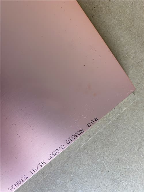
Rogers RO3010 is a ceramic-filled PTFE composite laminate with a dielectric constant (Dk) of 10.2 ± 0.30 at 10GHz and a low dissipation factor (Df) of 0.0022, offering exceptional high-frequency performance. This material is ideal for commercial microwave and RF applications requiring high dielectric constant and stable electrical properties.
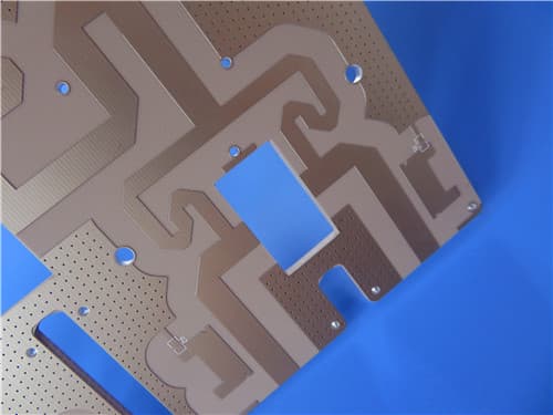
This 4-layer hybrid board combines two 1.27mm RO3010™ cores with a single sheet of 1080 FR-4 prepreg (0.076mm) in a symmetrical stackup. The symmetrical construction is specifically designed to minimize warpage caused by the CTE mismatch between the ceramic-filled PTFE cores and the FR-4 prepreg. The finished board is 2.8mm thick with 1oz copper on all layers and immersion tin surface finish.
2. Key Features of RO3010 Hybrid PCB
Dielectric Constant (Dk): 10.2 ± 0.30 @ 10GHz (process)
Design Dk: 11.20 (8 GHz - 40 GHz, differential phase length)
Dissipation Factor (Df): 0.0022 @ 10GHz/23°C
Thermal Coefficient of εr: -395 ppm/°C (-50°C to +150°C)
High Thermal Conductivity: 0.95 W/m/K @ 50°C
Low Moisture Absorption: 0.05%
CTE: X/Y=13/11 ppm/°C, Z=16 ppm/°C (-55°C to 288°C)
Decomposition Temperature (Td): 500°C
Symmetrical 4-layer hybrid stackup
Lead-Free Process Compatible, UL 94 V-0 flammability rating
Excellent dimensional stability
3. Benefits of RO3010 Hybrid PCB
High Dk (10.2±0.30) — Enables compact circuit designs with reduced physical dimensions
Low Df (0.0022 @ 10GHz) — Minimal signal loss for RF and microwave applications
Symmetrical Stackup — Minimizes warpage caused by CTE mismatch between RO3010 and FR-4
CTE Matched to Copper — X/Y CTE of 13/11 ppm/°C ensures excellent dimensional stability
High Thermal Conductivity (0.95 W/m/K) — Excellent heat dissipation for high-power applications
1080 Prepreg Selection — Thin, low-flow prepreg suitable for hybrid bonding
Immersion Tin Finish — Excellent solderability and corrosion resistance
4. PCB Construction Details
| Item | Specification |
|---|---|
| Base material (L1-L2) | Rogers RO3010™ (Ceramic-filled PTFE) 1.27mm core, Dk 10.2 ± 0.30 |
| Prepreg (between L2-L3) | 1080 FR-4 PP, 0.076mm |
| Base material (L3-L4) | Rogers RO3010™ (Ceramic-filled PTFE) 1.27mm core, Dk 10.2 ± 0.30 |
| Layer count | 4-layer |
| Board dimensions | 143mm x 97.5mm = 1 PCS |
| Finished board thickness | 2.8mm (nominal) |
| Finished Cu weight (outer) | 35μm (1 oz) |
| Finished Cu weight (inner) | 35μm (1 oz) |
| Surface finish | Immersion Tin |
| Solder mask | No |
| Silkscreen | White (both sides) |
| 100% Electrical test | Used prior to shipment |
| Quality standard | IPC-6012 Class 3 |
5. PCB Stackup (4-Layer Hybrid Structure)
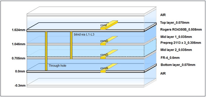
Layer 1 (Top): Copper, 35 μm (1 oz)
Dielectric: RO3010™ Core, 1.27 mm (Dk 10.2 ± 0.30 @ 10GHz)
Layer 2 (Inner): Copper, 35 μm (1 oz)
Prepreg: 1080 FR-4 PP, 0.076 mm
Layer 3 (Inner): Copper, 35 μm (1 oz)
Dielectric: RO3010™ Core, 1.27 mm (Dk 10.2 ± 0.30 @ 10GHz)
Layer 4 (Bottom): Copper, 35 μm (1 oz)
Total thickness: 2.8 mm

6. Technical Deep Dive: RO3010 + FR-4 Hybrid Stackup Design
6.1 4-Layer RO3010 + 1080 PP Hybrid Stackup Analysis: 1.27 + 0.076 + 1.27mm, 2.8mm Total Thickness Design Points
The stackup consists of two 1.27mm RO3010 cores bonded by a single 1080 FR-4 prepreg (0.076mm). This symmetrical construction (1.27 + 0.076 + 1.27mm) is critical for minimizing warpage. The total dielectric thickness before copper is 2.616mm, and with 1oz copper on all four layers (4 × 0.035mm = 0.14mm), the nominal finished thickness is approximately 2.756mm, which is rounded to 2.8mm in the design specification. The high Dk of RO3010 (10.2) allows for significant size reduction in RF circuits, while the thin 1080 prepreg provides a low-profile bond line with minimal impact on the overall electrical performance.
6.2 Rogers RO3010 and FR-4 PP Hybrid Lamination: 1080 Prepreg Selection and Lamination Risk Points
The 1080 prepreg is a critical choice for this hybrid stackup. With a nominal thickness of 0.076mm, it is thin enough to minimize the overall thickness contribution while still providing sufficient resin to bond the RO3010 cores. However, the 1080 prepreg has a relatively low resin content compared to thicker prepregs like 2116 or 7628, which can lead to insufficient flow and fill around heavy copper features. Lamination risks include:
Resin starvation: The low resin content of 1080 may not fully fill the etched areas on the inner layers, leading to voids or delamination.
Insufficient bonding: The PTFE surface of RO3010 is notoriously difficult to bond. Proper surface treatment (e.g., sodium etching) is required to achieve adequate peel strength.
CTE mismatch: The CTE of RO3010 (13/11 ppm/°C) is significantly lower than that of FR-4 (typically 50-70 ppm/°C), creating stress at the interface during thermal cycling.
Dimensional stability: RO3010 has a dimensional stability of -0.35/-0.31 mm/m, which must be considered when designing the artwork.
6.3 Heterogeneous Material Hybrid 4-Layer Board: CTE Matching Analysis of RO3010 Ceramic-Filled Substrate and FR-4 PP
The CTE mismatch between RO3010 and FR-4 is a major concern in hybrid designs. RO3010 has an X/Y CTE of 13/11 ppm/°C, while FR-4 typically has an X/Y CTE of 50-70 ppm/°C. This mismatch can cause significant stress at the bond line during thermal cycling, potentially leading to delamination or warpage. The Z-axis CTE of RO3010 is 16 ppm/°C, which is much lower than FR-4's Z-axis CTE of 50-60 ppm/°C. The thin 1080 prepreg (0.076mm) helps to minimize the overall CTE mismatch by reducing the volume of FR-4 in the stackup. Additionally, the symmetrical construction ensures that the CTE mismatch is balanced on both sides of the neutral axis, reducing warpage.
6.4 Symmetrical Stackup Improves Warpage of RO3010 Hybrid Board (Finished Thickness 2.8mm Example)
Warpage is a common problem in hybrid PCBs due to the CTE mismatch between different materials. In this 2.8mm thick example, the symmetrical stackup (1.27mm RO3010 + 0.076mm 1080 PP + 1.27mm RO3010) is essential for minimizing warpage. The neutral axis is located at the center of the 1080 prepreg, and the two RO3010 cores are identical in thickness and material properties. This symmetry ensures that the thermal expansion on both sides of the neutral axis is balanced, preventing the board from bowing or twisting during thermal cycling. Additionally, the thin 1080 prepreg minimizes the volume of FR-4, which is the primary source of CTE mismatch. Post-lamination cooling should be controlled to reduce residual stress.
6.5 1080-0.076mm PP for RO3010 High-Frequency Board: Resin Flow, Fill, and Interlayer Bonding Control
The 1080 prepreg is a thin, low-flow material that requires careful control of the lamination process to ensure proper resin flow, fill, and interlayer bonding. Key process parameters include:
Resin flow: The 1080 prepreg has a resin flow of approximately 10-15%, which is lower than thicker prepregs. This means that the prepreg may not completely fill large etched areas, leading to voids. To mitigate this, the inner layer copper should be kept as thin as possible (1oz is used here) and the etch patterns should be designed to minimize large open areas.
Fill: The 1080 prepreg must fill the gaps between the RO3010 cores and the copper features. Proper fill is essential for preventing delamination and ensuring reliable electrical performance.
Interlayer bonding: The bond strength between the RO3010 cores and the 1080 prepreg is critical. The RO3010 surface must be properly treated (sodium etching) to promote adhesion. The lamination cycle should be optimized to ensure complete cure of the prepreg and maximum bond strength.
7. Rogers RO3010 – Product Introduction
RO3010™ is a ceramic-filled PTFE composite laminate offering a dielectric constant (Dk) of 10.2 ± 0.30 at 10GHz and a low dissipation factor (Df) of 0.0022. The material features a thermal coefficient of εr of -395 ppm/°C, ensuring stable electrical performance across a wide temperature range (-50°C to +150°C). With a thermal conductivity of 0.95 W/m/K and a decomposition temperature (Td) of 500°C, RO3010™ provides excellent thermal management for high-frequency applications.
The material exhibits outstanding dimensional stability with X/Y CTE of 13/11 ppm/°C and Z-axis CTE of 16 ppm/°C (-55°C to 288°C), closely matched to copper for reliable plated through holes. Its low moisture absorption (0.05%) ensures consistent electrical performance in humid environments.
Key Material Properties:
Dk: 10.2 ± 0.30 @ 10GHz (process)
Df: 0.0022 @ 10GHz/23°C
TCDK: -395 ppm/°C (-50°C to +150°C)
Thermal Conductivity: 0.95 W/m/K @ 50°C
CTE X/Y: 13/11 ppm/°C, CTE Z: 16 ppm/°C (-55°C to 288°C)
Td: 500°C
Moisture Absorption: 0.05%
Flammability: UL 94 V-0
Lead-Free Process Compatible
8. Features and Benefits Summary
| Feature | Benefit |
|---|---|
| Dk 10.2 ± 0.30 @ 10GHz | High dielectric constant for compact circuit designs |
| Df 0.0022 @ 10GHz | Low loss for high-frequency RF and microwave designs |
| TCDK: -395 ppm/°C | Stable performance across temperature |
| CTE: 13/11/16 ppm/°C | Excellent dimensional stability, reliable plated through holes |
| Td: 500°C | Exceptional thermal stability for demanding applications |
| Symmetrical Stackup | Minimizes warpage caused by CTE mismatch |
| 1080 Prepreg | Thin bond line, minimal impact on electrical performance |
| Immersion Tin Finish | Excellent solderability and corrosion resistance |
9. RO3010 Typical Properties (Data Sheet)
| Property | Typical Value | Units | Test Conditions | Test Method |
|---|---|---|---|---|
| Electrical Properties | ||||
| Dielectric Constant (process) | 10.2 ± 0.30 | — | 23°C, 10 GHz | — |
| Dielectric Constant (design) | 11.20 | — | 8 GHz - 40 GHz | Differential Phase Length |
| Dissipation Factor | 0.0022 | — | 23°C, 10 GHz | — |
| Thermal Coefficient of Dielectric Constant | -395 | ppm/°C | -50 to 150°C, 10 GHz | — |
| Volume Resistivity | 10⁹ | MΩ-cm | Condition A | IPC TM-650 2.5.17.1 |
| Surface Resistivity | 10⁹ | MΩ | Condition A | IPC TM-650 2.5.17.1 |
| Thermal Properties | ||||
| Decomposition Temperature (Td) | 500 | °C | — | TGA-ASTM D3850 |
| Coefficient of Thermal Expansion - x | 13 | ppm/°C | -55 to 288°C, 23°C/50% RH | IPC TM-650 2.4.41 |
| Coefficient of Thermal Expansion - y | 11 | ppm/°C | -55 to 288°C, 23°C/50% RH | IPC TM-650 2.4.41 |
| Coefficient of Thermal Expansion - z | 16 | ppm/°C | -55 to 288°C, 23°C/50% RH | IPC TM-650 2.4.41 |
| Thermal Conductivity | 0.95 | W/(m.K) | 50°C | ASTM D5470 |
| Mechanical Properties | ||||
| Copper Peel Strength | 9.4 | lbs/in | 1 oz. EDC After Solder Float | IPC TM-650 2.4.8 |
| Young's Modulus | 1902 / 1934 | MPa | 23°C | ASTM D638 |
| Dimensional Stability (MD, CMD) | -0.35 / -0.31 | mm/m | Condition A | IPC TM-650 2.2.4 |
| Physical Properties | ||||
| Flammability | V-0 | — | — | UL 94 |
| Moisture Absorption | 0.05 | % | D48/50 | IPC TM-650 2.6.2.1 |
| Density | 2.8 | g/cm³ | 23°C | ASTM D792 |
| Specific Heat Capacity | 0.8 | J/g/K | — | Calculated |
| Lead Free Process Compatible | Yes | — | — | — |
10. Primary Application Areas
Microwave, RF, and radar systems
Phased array antennas
Band pass filters
Microstrip patch antennas
Voltage-controlled oscillators (VCOs)
Satellite communications and base station antennas
High-frequency RF and microwave circuits
11. Quality Assurance
Type of artwork supplied: Gerber RS-274-X
Accepted standard: IPC-6012 Class 3
Availability: Worldwide
100% Electrical test prior to shipment
ISO 9001:2015 & UL certified facility
12. Standard Thickness, Panel Sizes & Claddings
| Parameter | Options |
|---|---|
| Standard Thicknesses (RO3010) | 0.005" (0.13mm) ±0.0005", 0.010" (0.25mm) ±0.0007", 0.025" (0.64mm) ±0.0010", 0.050" (1.28mm) ±0.0020" |
| Standard Panel Sizes | 12"x18" (305x457mm), 24"x18" (610x457mm), 24"x21" (610x533mm) |
| Electrodeposited Copper Foil | ½ oz (18μm), 1 oz (35μm) |
Get a Quick Quote
Fill in the form below and our engineers will reply within 24 hours with technical specifications and pricing for 4-Layer Hybrid PCB with RO3010™ + FR-4.
.jpg)