What Makes WL-CT338 the Ideal Choice for High Frequency Circuit Boards
 October 3, 2025
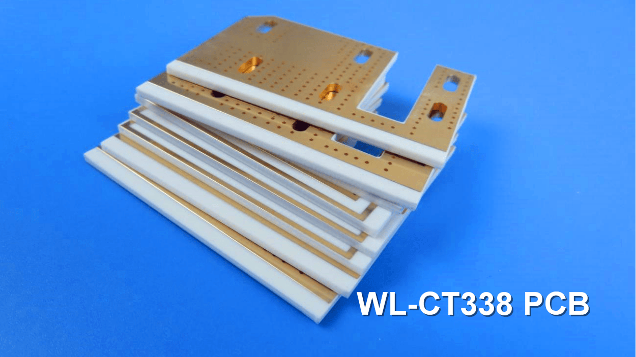
When it comes to high-performance electronics, the backbone of your device is often the printed circuit board (PCB). For applications demanding high frequency, low loss, and exceptional thermal stability, not just any PCB will do. That’s where the WL-CT series—and particularly the WL-CT338 High Frequency PCB—comes into play.
In this post, we’ll explore what makes the WL-CT338 material stand out, its key features, manufacturing capabilities, and the advanced applications it supports.
What Is the WL-CT Series?
The WL-CT series is a class of high-frequency laminates engineered for peak performance. By blending hydrocarbon resin, ceramic, and glass fiber cloth within a thermosetting resin system, these materials deliver the low-loss characteristics essential for high-frequency designs.
What does that mean in practice?
You get a material that offers not only minimal signal loss but also high temperature resistance, outstanding thermal stability, a consistent dielectric constant, a low coefficient of thermal expansion, and a remarkably high TG value—exceeding 280°C.
Key Features of WL-CT338 PCBs
1. Low Loss Performance:
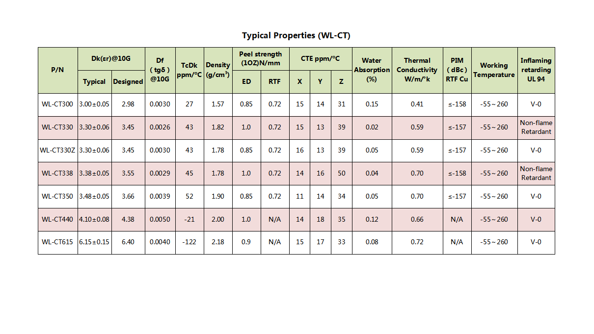
The dielectric constant (Dk) ranges from 3.0 to 6.15 across the series, with a dissipation factor (Df) between 0.003 and 0.005. For WL-CT338 specifically, expect a Dk of 3.38 and an impressively low Df of 0.0029.
2.Advanced Copper Cladding:
These laminates use a combination of forward-rotating ED copper and reverse-treated foil (TRF). Standard copper weights are 0.5 oz and 1 oz, with custom heavier weights available.
TRF foil includes an adhesive layer, making it about 7 mil thicker than standard ED copper, and offers strong peel strength of 0.72 N/mm.
3.Thermal Performance:
The CTE in the X/Y direction is closely matched to copper (11–18 ppm/°C), while the Z-direction expansion remains minimal (31–50 ppm/°C).
Thermal conductivity ranges from 0.41 to 0.72 W/mK, and water absorption is exceptionally low—between 0.02% and 0.15%.
PCB Manufacturing Capabilities with WL-CT338
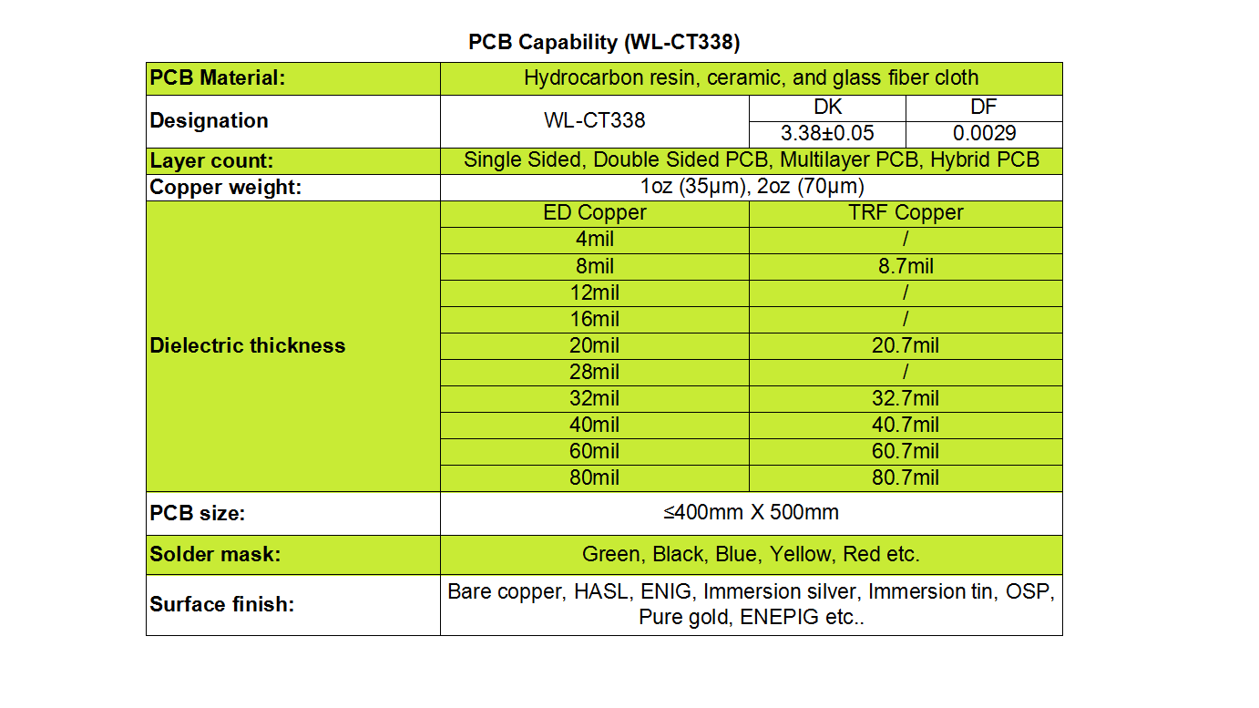
We support a wide range of PCB configurations and customizations using WL-CT338 material:
Layer Options: Single-sided, double-sided, multilayer, and hybrid PCBs
Copper Weight: Standard 1 oz and 2 oz finished copper, with flexibility for other requirements
Dielectric Thickness:
ED Copper: 4 mil to 80 mil。
TRF Copper: 8.7 mil to 80.7 mil
Max Board Size: Up to 400 mm × 500 mm
Solder Mask Colors: Green, black, blue, yellow, red, and more
Surface Finishes: Bare copper, HASL, ENIG, immersion silver, immersion tin, OSP, pure gold, and ENEPIG
Where Is WL-CT338 Used?
WL-CT338 PCBs are ideal for high-frequency and RF applications where reliability and signal integrity are non-negotiable. Common uses include:
Base station antennas
Satellite antennas
Automotive radar systems
WiMAX antennas
Distributed antenna systems (DAS)
Miniature patch antennas
Conclusion
Whether you're designing next-generation communication systems, automotive radar, or compact antenna solutions, WL-CT338 PCBs provide the thermal stability, low signal loss, and manufacturing versatility needed to bring high-frequency designs to life.
Interested in learning more or discussing how WL-CT338 can fit into your project? Stay tuned for more updates—and thanks for reading!