| |
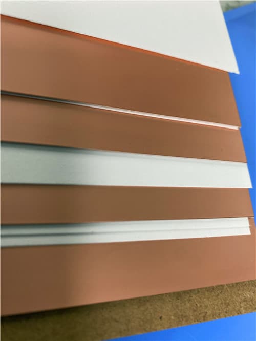
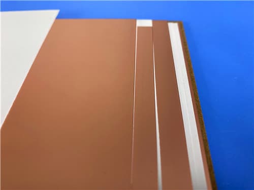
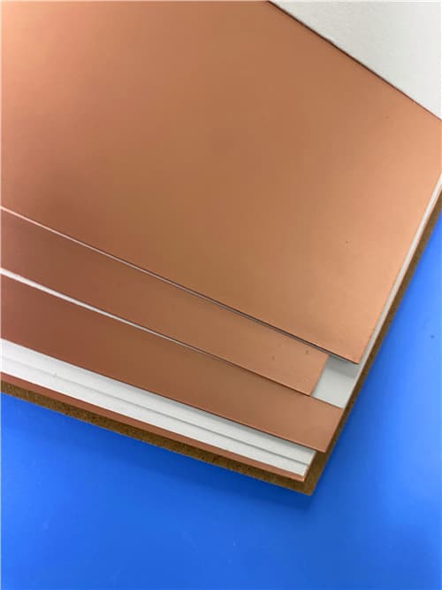
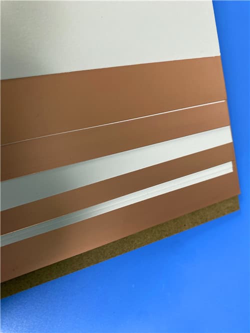
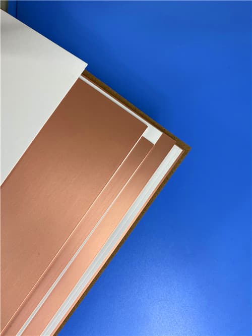
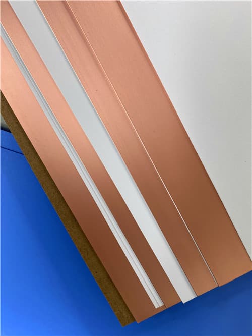
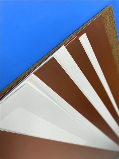
Rogers AD255C DK2.55 Df0.0013 (0.020-0.125") Antenna Grade Laminate
Brief Introduction
The AD Series antenna materials from Rogers Corporation are high-performance, specialty glass-reinforced PTFE-based laminates engineered for wireless antenna markets. AD255C provides controlled dielectric constant (2.55), low loss performance (Df 0.0013), and excellent passive intermodulation (PIM) performance. The woven glass reinforcement affords good circuit processability and enables high-yield circuit board fabrication.
Technical Features & Benefits
- Glass-Reinforced PTFE Composite: Provides excellent processability and mechanical strength for reliable PCB fabrication.
- Controlled Dielectric Constant: Dk = 2.55 ±0.04 at 10 GHz, ensuring consistent impedance control.
- Very Low Loss: Df of 0.0013 at 10 GHz, minimizing signal attenuation in high-frequency applications.
- Excellent Passive Intermodulation (PIM) Performance: -159/-163 dBc, critical for base station antennas and communication systems.
- Very Low Moisture Absorption: 0.03%, maintaining electrical properties in humid environments.
- Very High Copper Peel Strength: >13.6 lbs/in, ensuring reliable conductor adhesion.
- Available with Standard ED or Reverse-Treated ED Copper Foil Options: Flexibility for different application requirements.
- UL 94 V-0 Flammability Rating: Meets industry safety standards for flame resistance.
Typical Properties: AD255C
| Properties |
Typical Value |
Units |
Test Conditions |
Test Method |
| Electrical Properties | | | | |
| Dielectric Constant (process) | 2.55 | - | 23°C @ 50% RH, 10 GHz | IPC TM-650 2.5.5.5 |
| Dielectric Constant (design) | 2.60 | - | C-24/23/50, 10 GHz | Microstrip Differential Phase Length |
| Dissipation Factor | 0.0013 | - | 23°C @ 50% RH, 10 GHz | IPC TM-650 2.5.5.5 |
| Thermal Coefficient of Dk | -110 | ppm/°C | 0 to 100°C, 10 GHz | IPC TM-650 2.5.5.5 |
| Volume Resistivity | 7.4 x 10⁸ | MΩ·cm | C96/35/90 | IPC TM-650 2.5.17.1 |
| Surface Resistivity | 3.6 x 10⁷ | MΩ | C96/35/90 | IPC TM-650 2.5.17.1 |
| Electrical Strength | 911 | V/mil | - | IPC TM-650 2.5.6.2 |
| Dielectric Breakdown | >40 | kV | D-48/50, X/Y direction | IPC TM-650 2.5.6 |
| PIM² | -159 / -163 | dBc | Reflected 43 dBm swept tones at 1900 MHz S1/S1 | Rogers Internal 50 ohm |
| Thermal Properties | | | | |
| Decomposition Temperature (Td) | >500 | °C | 2hrs @ 105°C, 5% Weight Loss | IPC TM-650 2.3.40 |
| CTE - x | 34 | ppm/°C | -55°C to 288°C | IPC TM-650 2.4.41 |
| CTE - y | 26 | ppm/°C | -55°C to 288°C | IPC TM-650 2.4.41 |
| CTE - z | 196 | ppm/°C | -55°C to 288°C | IPC TM-650 2.4.41 |
| Thermal Conductivity | 0.35 | W/(m·K) | z direction | ASTM D5470 |
| Time to Delamination | >60 | minutes | as-received, 288°C | IPC TM-650 2.4.24.1 |
| Mechanical Properties | | | | |
| Copper Peel Strength | 2.4 (13.6) | N/mm (lbs/in) | 10s @ 288°C, 35 μm foil | IPC TM-650 2.4.8 |
| Flexural Strength (MD/CMD) | 60.7 / 44.1 (8.8 / 6.4) | MPa (ksi) | 25°C ± 3°C | ASTM D790 |
| Tensile Strength (MD, CMD) | 55.8 / 45.5 (8.1 / 6.6) | MPa (ksi) | 23°C @ 50% RH | ASTM D3039/D3039-14 |
| Flex Modulus | 6,412 / 5,640 (930 / 818) | MPa (ksi) | 25°C ± 3°C | IPC-TM-650 2.4.4 |
| Dimensional Stability (MD, CMD) | 0.03 / 0.07 | mils/inch | after etch + bake | IPC-TM-650 2.4.39a |
| Physical Properties | | | | |
| Flammability | V-0 | - | - | UL 94 |
| Moisture Absorption | 0.03 | % | E1/105 + D48/50 | IPC TM-650 2.6.2.1 |
| Density | 2.28 | g/cm³ | C24/23/50 | ASTM D792 |
| Specific Heat Capacity | 0.813 | J/g·°K | 2 hours at 105°C | ASTM E2716 |
Application Areas
- Base Station Antennas: Specifically engineered for today's wireless antenna markets requiring high performance and low PIM.
- Passive Components: Mixers, splitters, filters, and combiners for RF front-end systems.
- Feed Networks: Signal distribution networks for antenna arrays.
- RF Identification Tags: High-frequency RFID applications.
- Radar Systems: Automotive, defense, and weather radar applications.
- Mobile Communications Infrastructure: 4G/LTE and 5G base station equipment.
Available Configurations
- Standard Thicknesses: 0.020" (0.508 mm) +/- 0.002", 0.030" (0.762 mm) +/- 0.002", 0.040" (1.016 mm) +/- 0.002", 0.060" (1.524 mm) +/- 0.002", 0.125" (3.175 mm) +/- 0.006".
- Standard Panel Sizes: For 0.020": 18" x 12" (457mm x 305mm), 18" x 24" (457mm x 610mm). For all other thicknesses: 12" x 18" (305 x 457 mm), 24" x 18" (610 x 457 mm).
- Standard Claddings: Electrodeposited Copper Foil: ½ oz. (18µm), 1 oz. (35µm). Reverse Treated Electrodeposited Copper Foil: ½ oz. (18µm), 1 oz. (35µm).
- Custom Configurations: Contact Customer Service or Sales Engineering for other available product configurations including additional thicknesses, panel sizes and claddings.
|
|

.jpg)
