| |
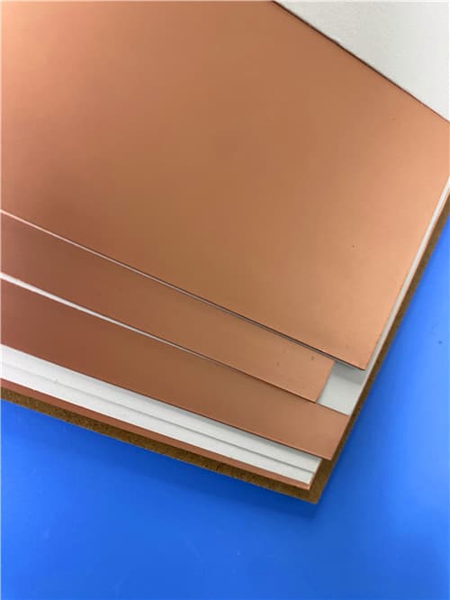
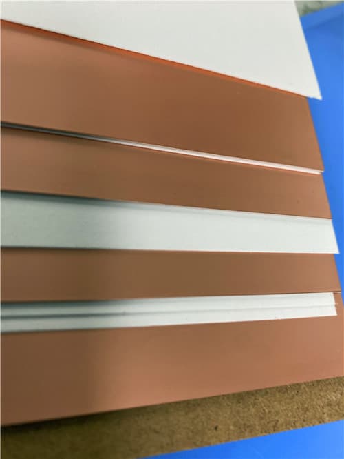
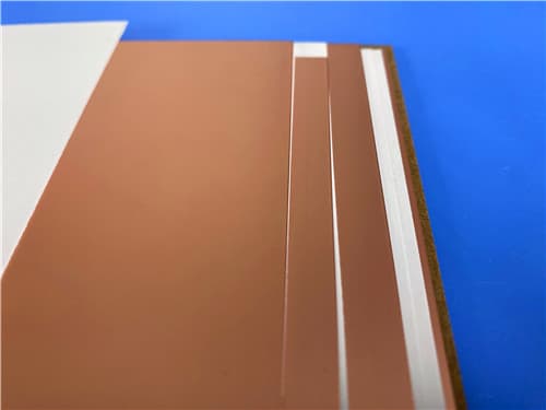
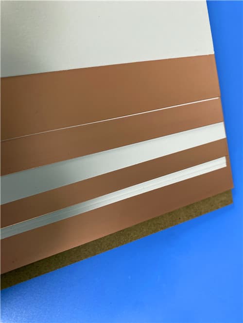
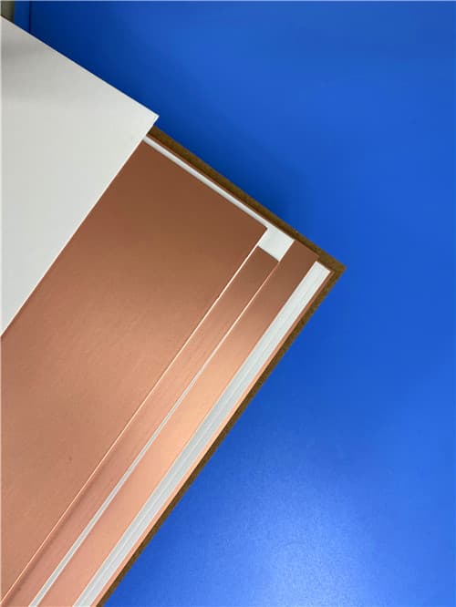
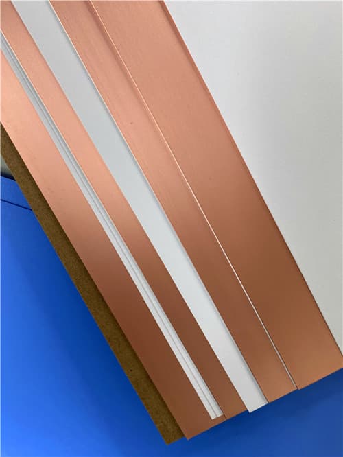
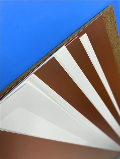
AGC TLX-8 DK2.55 Df0.0018 (0.064-6.35mm) PTFE/Woven Fiberglass Laminate
Brief Introduction
TLX-8 is a high-volume fiberglass-reinforced microwave substrate offering reliability in a wide range of RF applications. This versatile PTFE/fiberglass laminate features a dielectric constant range of 2.45-2.65 and is available in various thicknesses and copper claddings. It is suitable for low layer count microwave designs and serves as a workhorse in the RF microwave substrate world, particularly where mechanical reinforcement is required in severe environments.
Technical Features & Benefits
- Excellent PIM Values in PCBs: Measured lower than -160 dBc, ensuring superior intermodulation performance.
- Excellent Mechanical and Thermal Properties: Fiberglass reinforcement provides strength against vibration, high temperatures, and radiation.
- Low and Stable Dielectric Constant: Dk = 2.55 ±0.04 at 10 GHz for consistent electrical performance.
- Dimensionally Stable: Reliable fabrication and assembly with minimal movement.
- Low Moisture Absorption: Maintains electrical properties in humid environments.
- Tightly Controlled Dk (±0.04): Ensures repeatable circuit performance across panels and batches.
- Low Dissipation Factor: Df of 0.0018 at 10 GHz, minimizing signal loss.
- UL 94 V-0 Flammability Rating: Meets industry safety standards for flame resistance.
- For Low Layer Count Microwave Designs: Ideal for cost-effective, high-performance RF circuits.
- Long Space Heritage with NASA Low Outgassing Compliance: Suitable for aerospace and satellite applications.
- ~ ±2% Variation in Dk from -55°C to 125°C: Excellent thermal stability across wide temperature ranges.
Typical Properties: TLX-8
| Properties |
Conditions |
Typical Value |
Unit |
Test Method |
| Electrical Properties | | | | |
| Dielectric Constant | @ 10 GHz | 2.55 ± 0.04 | | IPC-650 2.5.5.3 |
| Dissipation Factor | @ 10 GHz | 0.0018 | | IPC-650 2.5.5.5.1 |
| Outgassing | % TML | 0.03 | 4 H 257 °F @ ≤ 5 x 10⁻⁵ Torr | ASTM E 595 |
| % CVCM | 0.00 | | |
| % WVR | 0.01 | | |
| Surface Resistivity | | 6.605 x 10⁸ | MΩ | IPC-650 2.5.17.1 Sec. 5.2.1 (Elevated Temp.) |
| | 3.550 x 10⁶ | MΩ | IPC-650 2.5.17.1 Sec. 5.2.1 (Humidity Cond.) |
| Volume Resistivity | | 1.110 x 10¹⁰ | MΩ·cm | IPC-650 2.5.17.1 Sec. 5.2.1 (Elevated Temp.) |
| | 1.046 x 10¹⁰ | MΩ·cm | IPC-650 2.5.17.1 Sec. 5.2.1 (Humidity Cond.) |
| Dimensional Stability | MD | 0.06 | mm/m (mils/in) | IPC-650 2.4.39 Sec. 5.4 (After Bake) |
| CD | 0.08 | mm/m (mils/in) | |
| MD | 0.09 | mm/m (mils/in) | IPC-650 2.4.39 Sec. 5.5 (Thermal Stress) |
| CD | 0.10 | mm/m (mils/in) | |
| Thermal Properties | | | | |
| Thermal Conductivity | | 0.19 | W/m·K | ASTM F433/ASTM 1530-06 |
| CTE (25-260°C) | X | 21 | ppm/°C | IPC-650 2.4.41/ASTM D 3386 |
| Y | 23 | ppm/°C | |
| Z | 215 | ppm/°C | |
| Td | 2% Weight Loss | 535 | °C | IPC-650 2.4.24.6 (TGA) |
| 5% Weight Loss | 553 | °C | |
| Mechanical Properties | | | | |
| Peel Strength | 1 oz. ED | 2.63 (15) | N/mm (lbs/in) | IPC-650 2.4.8 Sec. 5.2.2 (Thermal Stress) |
| 1 oz. RTF | 2.98 (17) | N/mm² (kpsi) | |
| ½ oz. ED | 2.45 (14) | N/mm² (kpsi) | IPC-650 2.4.8.3 (Elevated Temp.) |
| ½ oz. ED | 1.93 (11) | N/mm² (kpsi) | IPC-650 2.4.8 Sec. 5.2.2 (Thermal Stress) |
| 1 oz. rolled | 2.28 (13) | N/mm² (kpsi) | |
| Young's Modulus | MD | 6,757 (980) | N/mm² (psi) | ASTM D 902 |
| CD | 8,274 (1,200) | N/mm² (psi) | |
| MD | 11,238 (1,630) | N/mm² (psi) | ASTM D 3039 |
| Chemical/Physical Properties | | | | |
| Moisture Absorption | | 0.02 | % | IPC-650 2.6.2.1 |
| Dielectric Breakdown | | > 45 | kV | IPC-650 2.5.6 |
| Flammability Rating | | V-0 | | UL-94 |
Application Areas
- Antennas: Phased array, patch, and other high-frequency antenna designs.
- Mixers, Splitters, Filters & Combiners: Passive RF components requiring low loss.
- Passive Components: General-purpose RF circuits and devices.
- Radar Systems: Automotive, defense, and weather radar applications.
- Mobile Communications: Base stations and backhaul equipment.
- Microwave Test Equipment: Calibration standards and test fixtures.
- Microwave Transmission Devices: High-frequency signal distribution.
- RF Components: General high-frequency circuit designs.
- Applications Requiring Resistance to Severe Environments: Space launch vibration, high temperature exposure, radiation resistance, extreme maritime conditions, wide temperature ranges during flight.
Available Configurations
- Dielectric Thickness Range: 0.0025" - 0.250" (0.064 mm - 6.35 mm); can be manufactured in increments of 0.005" (0.125 mm).
- Standard Panel Size: 18" x 24" (457 mm x 610 mm).
- Available Sheet Sizes: 12" x 18" (305 x 457 mm), 16" x 18" (406 x 457 mm), 18" x 24" (457 x 610 mm), 16" x 36" (406 x 914 mm), 24" x 36" (610 x 914 mm), 18" x 48" (457 x 1,220 mm), 36" x 48" (914 x 1,220 mm).
- Copper Cladding: Various options available including ED, RTF, and rolled copper foils.
- Custom Configurations: Contact AGC for availability of additional thicknesses, other sizes, and other types of cladding.
|
|
.jpg)
