| |
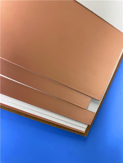
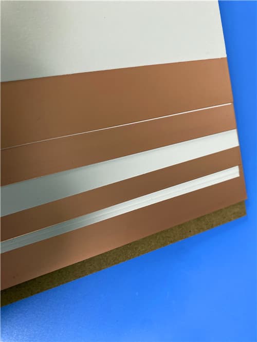
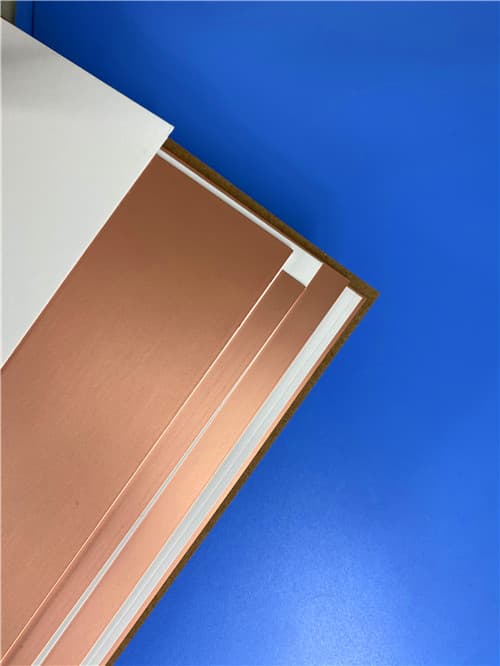
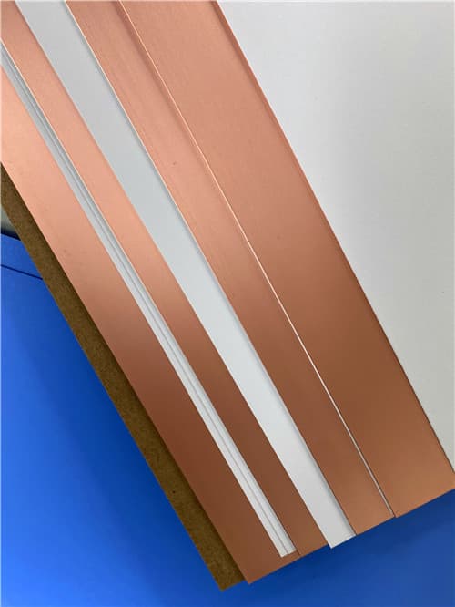
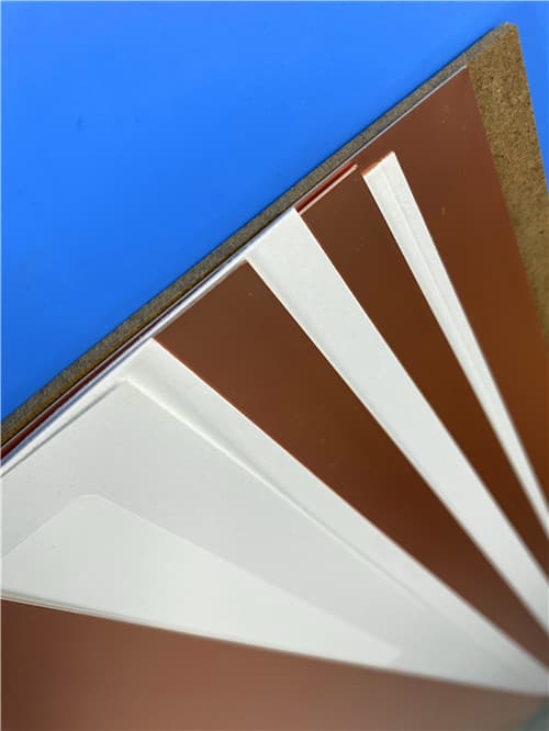
Wangling F4BTMS255 DK2.55 Df0.0012 (0.127-6.35mm+) Ceramic-Filled PTFE Laminate
Brief Introduction
F4BTMS series is an upgraded version of the F4BTM series, featuring significant technological breakthroughs in material formulation and manufacturing processes. The material incorporates a high volume of uniformly dispersed ceramic fillers combined with ultra-thin, fine-weave fiberglass reinforcement. F4BTMS255 is an aerospace-grade, high-reliability material that serves as a domestic alternative to similar international products. The advanced composition minimizes glass weave effects during electromagnetic wave propagation, reduces dielectric loss, enhances dimensional stability, and improves anisotropy in the X/Y/Z directions, enabling higher operating frequencies and increased electrical strength.
Technical Features & Benefits
- Tight Dielectric Constant Tolerance: Excellent batch-to-batch consistency for reliable circuit design and manufacturing.
- Ultra-Low Dissipation Factor: Df of 0.0012 at 10 GHz, minimizing signal attenuation in high-frequency applications.
- Stable Dk and Low Loss up to 40GHz: Suitable for phase-sensitive applications requiring consistent performance across frequency.
- Excellent Thermal Stability of Dk and Df from -55°C to 150°C: Reliable operation across wide temperature ranges.
- Superior Radiation Resistance: Maintains stable electrical and physical properties after irradiation for aerospace and defense applications.
- Low Outgassing: Meets space vacuum requirements for satellite and spaceborne equipment.
- Low CTE in X/Y/Z Directions: Provides excellent thermal stability and plated-through hole reliability.
- Enhanced Thermal Conductivity: 0.31 W/(m·K) for higher power applications and improved heat dissipation.
- Excellent Dimensional Stability: Ensures reliable fabrication and assembly processes.
- Very Low Moisture Absorption: Maintains electrical properties in humid environments.
Typical Properties: F4BTMS255
| Property |
Test Condition |
Unit |
F4BTMS255 |
| Electrical Properties | | | |
| Dielectric Constant (Typical) | 10 GHz | – | 2.55 |
| Dielectric Constant Tolerance | – | – | ±0.04 |
| Dielectric Constant (Design) | 10 GHz | – | 2.55 |
| Dissipation Factor (Typical) | 10 GHz | – | 0.0012 |
| 20 GHz | – | 0.0013 |
| 40 GHz | – | 0.0016 |
| Dielectric Constant Temp. Coeff. | -55°C to 150°C | ppm/°C | -92 |
| Peel Strength | 1 oz RTF Copper | N/mm | >1.8 |
| Volume Resistivity | Normal | MΩ·cm | ≥1×10⁸ |
| Surface Resistance | Normal | MΩ | ≥1×10⁸ |
| Electric Strength (Z-direction) | 5 kW, 500 V/s | kV/mm | >32 |
| Breakdown Voltage (XY-direction) | 5 kW, 500 V/s | kV | >40 |
| Thermal & Mechanical Properties | | | |
| CTE (X, Y-direction) | -55°C to 288°C | ppm/°C | 15~20 |
| CTE (Z-direction) | -55°C to 288°C | ppm/°C | 80 |
| Thermal Stress | 260°C, 10s, 3 cycles | – | No Delamination |
| Water Absorption | 20±2°C, 24 hours | % | 0.025 |
| Density | Room Temperature | g/cm³ | 2.26 |
| Long-term Operating Temperature | – | °C | -55 to +260 |
| Thermal Conductivity (Z-direction) | Z-direction | W/(m·K) | 0.31 |
| Flammability | – | UL-94 | V-0 |
| Material Composition | – | – | PTFE, Ultra-thin Fine-weave Fiberglass, Ceramic Fillers |
Application Areas
- Aerospace Equipment, Spaceborne and Onboard Equipment: High-reliability applications requiring radiation resistance and low outgassing.
- Microwave and RF Systems: High-frequency signal processing and transmission.
- Radar, Military Radar: Phased array antennas and detection systems.
- Feed Networks: Signal distribution for antenna arrays.
- Phase-Sensitive Antennas, Phased Array Antennas: Where stable Dk and low loss are critical.
- Satellite Communications: Ground terminals and spaceborne transceivers.
Available Configurations
- Copper Foil Options: Standard RTF low-profile copper foil; 0.5 oz (0.018mm), 1 oz (0.035mm); other thicknesses available upon request. Optional 50Ω embedded resistor foil, aluminum base, or copper base available.
- Standard Panel Sizes: 305×460mm (12×18"), 460×610mm (18×24"), 610×920mm (24×36"); custom sizes available upon request.
- Dielectric Thickness Options: Minimum thickness 0.127mm, available in 0.127mm multiples. Available thicknesses include: 0.127mm, 0.254mm, 0.508mm, 0.635mm, 0.762mm, 0.787mm, 1.016mm, 1.270mm, 1.50mm, 1.524mm, 1.575mm, 2.03mm, 2.54mm, 3.175mm, 4.06mm, 5.08mm, 6.35mm. Tolerances range from ±0.0127mm to ±0.25mm depending on thickness.
- Metal Base Options: Available with aluminum or copper backing for shielding or heat dissipation (F4BTMS255-AL or F4BTMS255-CU). Copper base (purple brass/brass): Thermal conductivity 380 W/(m·K), CTE 17 ppm/°C. Aluminum base: Thermal conductivity 180 W/(m·K), CTE 24 ppm/°C.
|
|
.jpg)
.jpg)
