F4BTM298 High Frequency PCB 3.0mm Substrates RF PCB Board with Immersion Tin
(Printed Circuit Boards are custom-made products; the images and specifications provided are for reference only.)
General Description
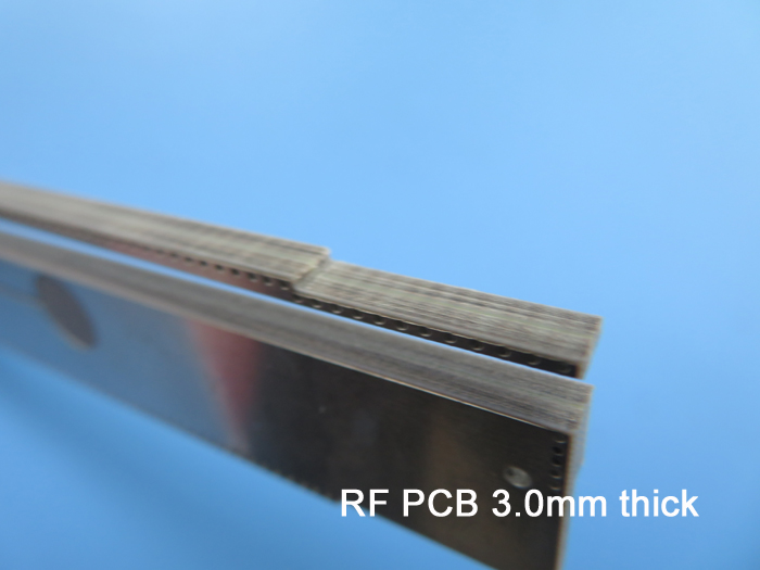
The F4BTM298 is a high-frequency, double-sided PCB specifically designed for patch antenna applications and constructed on a 3.0mm substrate.
Basic Specifications
| Item | Specification |
|---|---|
| Base Material | F4BTM298 |
| Dielectric Constant | 2.98 ± 0.06 |
| Layer Count | 2 Layers |
| Type | Through holes |
| Dimensions | 110mm x 35mm (1 type = 1 piece) |
| Surface Finish | Immersion tin |
| Copper Weight | Outer layer 35 μm |
| Solder Mask / Legend | None / None |
| Final PCB Height | 3.1 mm |
| Standard Compliance | IPC 6012 Class 2 |
| Packing | 20 pieces per shipment |
| Lead Time | 7 working days |
| Shelf Life | 6 months |
Applications
.Multiplexer
.Acoustic Detection Sensors
.Radio Frequency (RF)
.RF Transceiver
F4BTM High Frequency Laminates
The F4BTM series of high-frequency materials are composed of glass fiber cloth, nano-ceramic fillers, and polytetrafluoroethylene resin, developed through rigorous preparation and precise pressing processes.
This series of products builds upon the F4BM dielectric layer, added with high-dielectric, low-loss nanoscale ceramics, resulting in superior dielectric constants, improved heat resistance, lower thermal expansion coefficients, higher insulation resistance, and enhanced thermal conductivity—all while preserving low loss characteristics.
Our PCB Capability (F4BTM)
PCB Capability (F4BTM) |
|||
PCB Material: |
PTFE / glass fiber cloth / Nano-ceramic filler |
||
Designation (F4BTM ) |
F4BTM |
DK (10GHz) |
DF (10 GHz) |
F4BTM298 |
2.98±0.06 |
0.0018 |
|
F4BTM300 |
3.0±0.06 |
0.0018 |
|
F4BTM320 |
3.2±0.06 |
0.0020 |
|
F4BTM350 |
3.5±0.07 |
0.0025 |
|
Layer count: |
Single Sided, Double Sided PCB, Multilayer PCB, Hybrid PCB |
||
Copper weight: |
0.5oz (17 µm), 1oz (35µm), 2oz (70µm) |
||
Dielectric thickness (or overall thickness) |
0.25mm, 0.508mm, 0.762mm, 0.8mm, 1.0mm, 1.016mm, 1.27mm, 1.524mm, 2.0mm, 3.0mm, 4.0mm, 5.0mm, 6.0mm, 8.0mm, 10.0mm, 12.0mm |
||
PCB size: |
≤400mm X 500mm |
||
Solder mask: |
Green, Black, Blue, Yellow, Red etc. |
||
Surface finish: |
Bare copper, HASL, ENIG, Immersion silver, Immersion tin, OSP, Pure gold, ENEPIG etc.. |
||
Data Sheet (F4BTM)
Product Technical Parameters |
Product Models & Data Sheet |
||||||
Product Features |
Test Conditions |
Unit |
F4BTM298 |
F4BTM300 |
F4BTM320 |
F4BTM350 |
|
Dielectric Constant (Typical) |
10GHz |
/ |
2.98 |
3.0 |
3.2 |
3.5 |
|
Dielectric Constant Tolerance |
/ |
/ |
±0.06 |
±0.06 |
±0.06 |
±0.07 |
|
Loss Tangent (Typical) |
10GHz |
/ |
0.0018 |
0.0018 |
0.0020 |
0.0025 |
|
20GHz |
/ |
0.0023 |
0.0023 |
0.0026 |
0.0035 |
||
Dielectric Constant Temperature Coefficient |
-55 º~150ºC |
PPM/℃ |
-78 |
-75 |
-75 |
-60 |
|
Peel Strength |
1 OZ F4BTM |
N/mm |
>1.6 |
>1.6 |
>1.6 |
>1.6 |
|
1 OZ F4BTME |
N/mm |
>1.4 |
>1.4 |
>1.4 |
>1.4 |
||
Volume Resistivity |
Standard Condition |
MΩ.cm |
≥1×10^7 |
≥1×10^7 |
≥1×10^7 |
≥1×10^7 |
|
Surface Resistivity |
Standard Condition |
MΩ |
≥1×10^6 |
≥1×10^6 |
≥1×10^6 |
≥1×10^6 |
|
Electrical Strength (Z direction) |
5KW,500V/s |
KV/mm |
>26 |
>30 |
>32 |
>32 |
|
Breakdown Voltage (XY direction) |
5KW,500V/s |
KV |
>34 |
>35 |
>40 |
>40 |
|
Coefficientof Thermal Expansion |
XY direction |
-55 º~288ºC |
ppm/ºC |
15,16 |
15,16 |
13,15 |
10,12 |
Z direction |
-55 º~288ºC |
ppm/ºC |
78 |
72 |
58 |
51 |
|
Thermal Stress |
260℃, 10s,3 times |
No delamination |
No delamination |
No delamination |
No delamination |
||
Water Absorption |
20±2℃, 24 hours |
% |
≤0.05 |
≤0.05 |
≤0.05 |
≤0.05 |
|
Density |
Room Temperature |
g/cm3 |
2.25 |
2.25 |
2.20 |
2.20 |
|
Long-Term Operating Temperature |
High-Low Temperature Chamber |
℃ |
-55~+260 |
-55~+260 |
-55~+260 |
-55~+260 |
|
Thermal Conductivity |
Z direction |
W/(M.K) |
0.42 |
0.42 |
0.50 |
0.54 |
|
PIM |
Only applicable to F4BTME |
dBc |
≤-160 |
≤-160 |
≤-160 |
≤-160 |
|
Flammability |
/ |
UL-94 |
V-0 |
V-0 |
V-0 |
V-0 |
|
Material Composition |
/ |
/ |
PTFE, Fiberglass Cloth, nano-ceramics |
||||