Hybrid High Frequency Multilayer PCB 6-Layer PCB Built on 12mil RO4003C and FR-4
(Printed circuit boards are custom-made products; the images and parameters shown are for reference only)
Introduction
Hello Everyone,
Warm greetings!
Today, we are introducing a 6-layer RF PCB constructed using 12mil RO4003C and FR-4. This board is specifically designed for satellite antenna applications. Below is the stack-up diagram of the board.
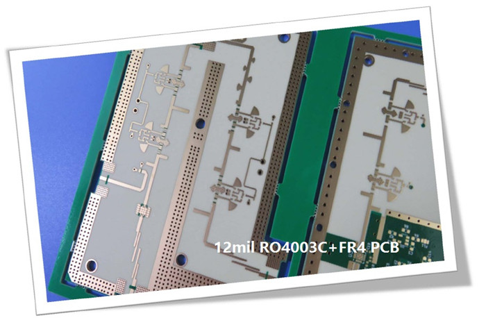
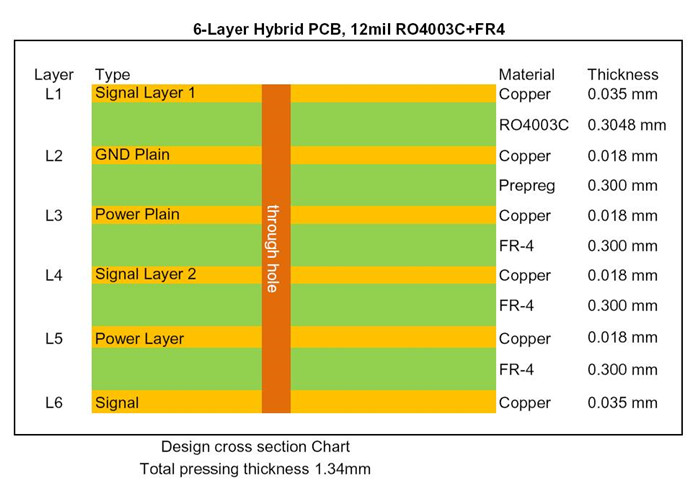
In the stack-up, the 12mil core is positioned on the top layer, primarily serving as the signal layer. The fixed thickness of this core is crucial for maintaining the electrical length of RF lines on the circuit board. The remaining layers consist of FR-4 epoxy glass material, which matches the thickness of the RO4003C core.
First Board: Satellite Receiver Application
Detailed Specifications
| Specification | Details |
|---|---|
| Base Material | 12mil (0.305mm) RO4003C + Tg170 FR-4 |
| Dielectric Constant | 3.38 +/- 0.05 |
| Layer Count | 6 layers |
| Via Type | Through holes |
| Format | 105mm x 80mm = 1 type = 1 piece |
| Surface Finish | Immersion gold |
| Copper Weight | Outer layer 35μm / Inner layer 18μm |
| Solder Mask / Legend | Green / White |
| Final PCB Height | 1.4 mm |
| Other Features | Impedance controlled PCB |
| Standard | IPC 6012 Class 2 |
| Packing | 20 panels per shipment |
| Lead Time | 10 working days |
| Shelf Life | 6 months |
Mature Mixed Pressing Materials
Currently, the following mixed materials are being utilized:
RO4350B + FR-4
RO4003C + FR-4
F4B + FR-4
RT/duroid 5880 + RO4350B
RT/duroid 5880 + FR-4
Thank you for reading! We welcome your inquiries regarding RF PCBs.
Appendix: Our PCB Capability 2024
Factory Process Capability (2024) |
|
Substrate Types and Brands |
Standard FR-4, High Tg FR-4, High Frequency Materials, Polyimide/PET flexible Materials |
Shengyi, ITEQ, Isola, Taiwan Union, Rogers Corp. Taconic, Panasonic |
|
Board Types |
Rigid PCB, Flexible Circuits, Rigid-Flex PCB, Hybrid PCB, HDI PCB |
CCL Model |
High Tg FR-4: S1000-2M, TU-872 SLK, TU-768, IT-180A |
Rogers Corp: RO4350B, RO4003C, RO4725JXR, RO4730G3, RO4360G2, RO4533, RO4534, RO4535, RO4830, RO4835, RO3003, RO3006, RO3010, RO3035, RO3203, RO3210; RT/Duriod 5880; RT/Duriod 5870, RT/Duriod 6002, RT/duroid 6006, RT/Duroid 6010.2LM, RT/duroid 6035HTC; RT/duroid 5880LZ, RT/duroid 6202; TMM3, TMM4, TMM6, TMM10, TMM10i, TMM13i, Kappa 438; AD250C, AD255C, AD300D, AD350A, AD450, AD600, AD1000, TC350; TC600; DiClad 880, DiClad 870, DiClad 527; IsoClad 917, IsoClad 933; CLTE-XT, CLTE-AT, CLTE-MW; CuClad 217, CuClad 233, CuClad 250. |
|
Taconic: TLF-35; RF-35TC, RF-60A, RF-60TC, RF-35A2,RF-30, RF-35, RF-45, RF-10, TRF-45; TLX-0, TLX-6, TLX-7, TLX-8; TLX-9, TLY-3, TLY-5, TLY-5Z; CER-10; TSM-DS3 |
|
Wangling: F4BM217, F4BM220, F4BM233, F4BM245, F4BM255, F4BM265, F4BM275, F4BM294, F4BM300; |
|
Maximum Delivery Size |
1200mm x 572 mm |
Minimum Finished Board Thickness |
L≤2L: 0.15mm; 4L: 0.4mm |
Maximum Finished Board Thickness |
10.0 mm |
Blind Buried Holes (Non-crossing) |
0.1mm |
Maximum Hole Aspect Ratio |
15:01 |
Minimum Mechanical Drill Hole Diameter |
0.1 mm |
Through-hole Tolerance |
+/- 0.0762 mm |
Press-fit Hole Tolerance |
+/- 0.05mm |
Non-plated Copper Hole Tolerance |
+/- 0.05mm |
Maximum Number of Layers |
32 |
Internal and External Layer Maximum Copper Thickness |
12Oz |
Minimum Drill Hole Tolerance |
+/- 2mil |
Minimum Layer-to-Layer Tolerance |
+/- 3mil |
Minimum Line Width/Spacing |
3mil/3mil |
Minimum BGA Diameter |
8mil |
Impedance Tolerance |
< 50Ω ±5Ω; ≥50Ω±10% |
Surface Treatment Processes |
Leaded/Lead-free HASL, Immersion Gold, Immersion Silver, Immersion Tin, OSP, ENIG, ENEPIG, Pure gold, Carbon Ink, Peelable Mask, Gold Finger, etc. |
