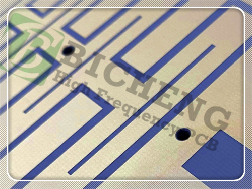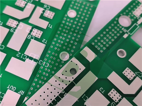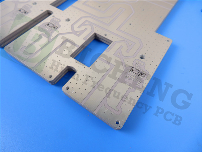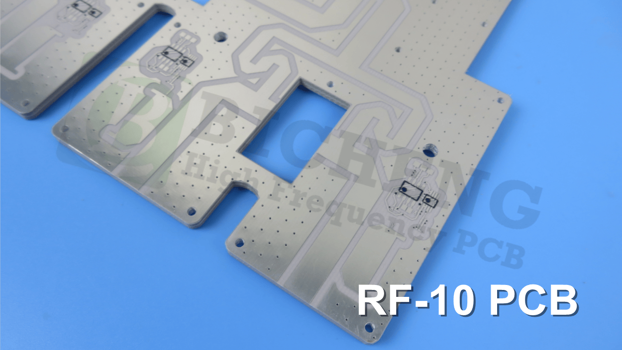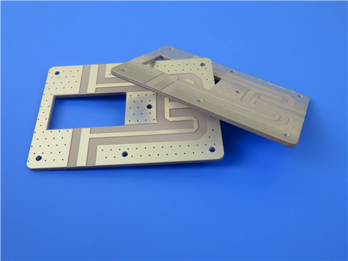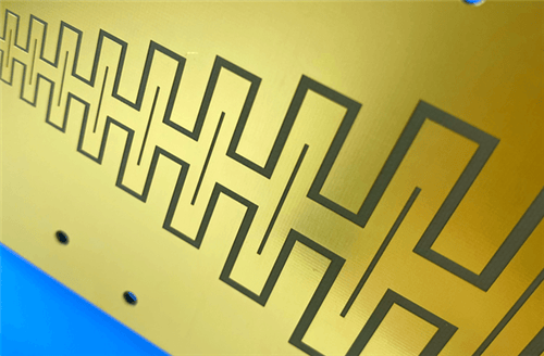
AGC RF-10 2-Layer 0.5mm ENEPIG PCB – Microstrip Patch & GPS Antenna1. Introduction to AGC RF-10 PCB AGC RF-10 copper clad laminates are composites of ceramic-filled PTFE and woven fiberglass, engineered for high-power RF applications. RF-10 offers the advantage of a high dielectric constant (Dk) and low dissipation factor, enabling significant size reduction in RF circuits. The thin woven fiberglass reinforcement provides both low dielectric loss and improved rigidity, facilitating ease of handling and enhanced dimensional stability for multilayer circuits. AGC RF-10 laminates are designed to provide a cost-effective substrate with industry-acceptable delivery times. They bond well to smooth, low-profile copper, and the combination of low dissipation factor and very smooth copper results in optimal insertion losses at higher frequencies where skin effect losses are substantial. This 2-layer rigid PCB is constructed entirely with AGC RF-10 as the core material, making it ideal for demanding RF antenna and passive component applications.
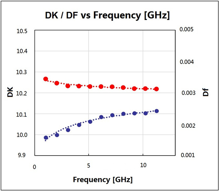
2. Key Features of AGC RF-10 PCB High dielectric constant (Dk = 10.2 ± 0.3 at 10 GHz) Low dissipation factor (Df = 0.0025 at 10 GHz) High thermal conductivity (0.85 W/m·K, unclad) Low moisture absorption (0.08%) X-axis CTE: 16 ppm/°C, Y-axis CTE: 20 ppm/°C, Z-axis CTE: 25 ppm/°C Flammability rating: UL 94 V-0 3. Benefits of AGC RF-10 PCB High Dk enables RF circuit size reduction Excellent dimensional stability Tight Dk tolerance (±0.3) High thermal conductivity for enhanced thermal management Excellent adhesion to smooth copper foils Low X, Y, Z expansion for plated through-hole reliability Excellent price/performance ratio 4.AGC RF-10 PCB Construction Details
5. PCB Stackup (2-Layer Rigid Structure) Copper_layer_1 - 35μm (1oz) RF-10 Core - 10mil (0.254mm) Copper_layer_2 - 35μm (1oz) 6. PCB Statistics Components: 24 Total Pads: 51 Thru Hole Pads: 34 Top SMT Pads: 17 Bottom SMT Pads: 0 Vias: 29 Nets: 2 7. Primary Application Areas Microstrip patch antennas GPS antennas Passive components (filters, couplers, power dividers) Aircraft collision avoidance systems Satellite components 8.Quality Assurance Type of artwork supplied: Gerber RS-274-X 9. AGC RF-10 Low-Loss Ceramic-Filled PTFE – Product Introduction AGC RF-10 laminates are ceramic-filled PTFE composites reinforced with woven fiberglass. They are optimized for high-frequency, high-power RF applications requiring high dielectric constant and low signal loss. The thin woven glass reinforcement ensures mechanical rigidity and dimensional stability, while the ceramic filler provides a stable Dk and low dissipation factor. AGC RF-10 can be sheared, drilled, milled, and plated using standard PTFE circuit board processing techniques. Its low Z-axis expansion enhances plated through-hole reliability and reduces scaling factors for artwork compensation.
10.Features and Benefits Summary
11.AGC RF-10 Data Sheet
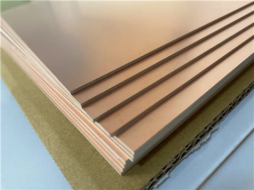
12.Some Typical Applications Microstrip patch antennas 13. Standard Thicknesses, Panel Sizes & Claddings Standard Thicknesses (Available)
Available Sheet Sizes
|
Get a Quick Quote
Fill in the form below and our engineers will reply within 24 hours with technical specifications and pricing for AGC RF-10 2-Layer 0.5mm ENEPIG PCB.