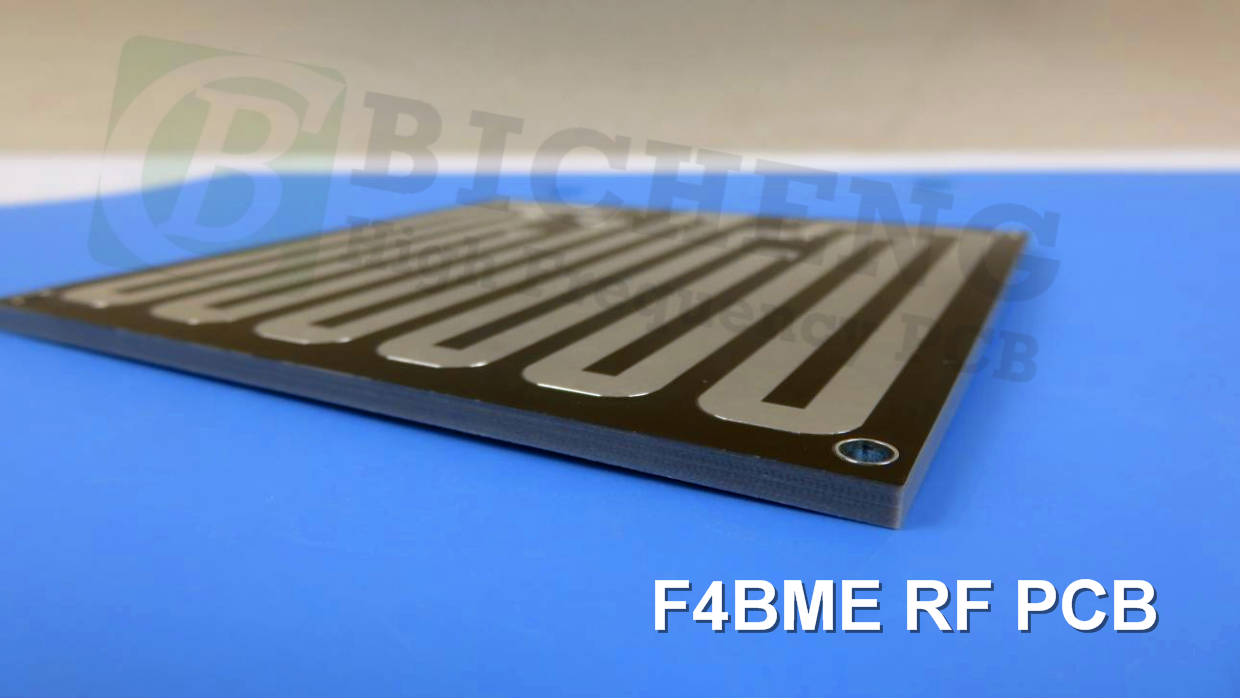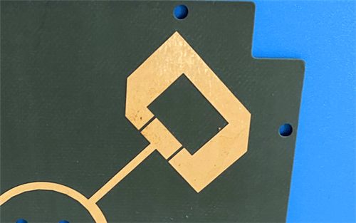
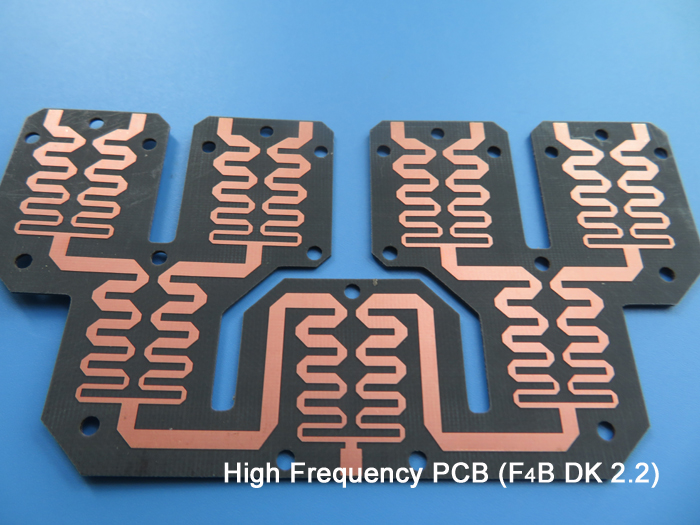
Wangling F4BME217 2-Layer 1.3mm Bare Copper PCB – Microwave & RF Applications1. Introduction to Wangling F4BME217 PCB Wangling's F4BME217 is a high-performance PTFE composite laminate engineered for demanding RF and microwave applications. Precision-formulated from woven fiberglass cloth, PTFE resin, and film, it delivers superior, consistent electrical properties. This next-generation material significantly outperforms its predecessor, F4B220, offering lower dielectric loss, higher insulation resistance, and enhanced stability. It serves as a reliable, high-performance domestic substitute for comparable imported laminates. F4BME217 is clad with Reverse-Treated Foil (RTF) copper. This configuration provides superior low-PIM performance, enables more precise etching for fine-line circuits, and reduces conductor loss, making it ideal for high-precision designs. This 2-layer rigid PCB is constructed entirely with Wangling F4BME217 as the core material, making it ideal for demanding microwave, RF, radar, and satellite communication applications.
2. Key Features of Wangling F4BME217 PCB Dielectric constant of 2.17 at 10 GHz (Dk range 2.17 to 3.0 available, customizable) Low dissipation factor of 0.001 at 10 GHz and 0.0014 at 20 GHz Low PIM value of ≤ -159 dBc (F4BME with RTF copper) High electrical strength of >23 KV/mm (Z direction) Low moisture absorption of ≤0.08% Flammability rating: UL 94 V-0 Anti-radiation and low outgassing properties Wide operating temperature range: -55°C to +260°C 3. Benefits of Wangling F4BME217 PCB Low dielectric loss for high-frequency performance High insulation resistance and enhanced stability Superior low-PIM performance with RTF copper More precise etching for fine-line circuits Reduced conductor loss Excellent dimensional stability Low thermal expansion coefficient and reduced temperature drift Cost-effective domestic substitute for imported laminates 4.Wangling F4BME217 PCB Construction Details
5. PCB Stackup (2-Layer Rigid Structure) Copper_layer_1 - 35 μm (1 oz) F4BME217 Core - 1.0 mm (39.37 mil) Copper_layer_2 - 35 μm (1 oz) 6. PCB Statistics Components: 15 Total Pads: 42 Thru Hole Pads: 17 Top SMT Pads: 25 Bottom SMT Pads: 0 Vias: 28 Nets: 7 7. Primary Application Areas Microwave, RF, and radar Phase shifters and passive components Power dividers, couplers, and combiners Feed networks and phased array antennas Satellite communication and base station antennas 8.Quality Assurance Type of artwork supplied: Gerber RS-274-X Accepted standard: IPC-Class-3 Availability: Worldwide 9. Wangling F4BME217 Low-Loss PTFE Composite – Product Introduction F4BME217 is a high-performance PTFE composite laminate engineered for demanding RF and microwave applications. Precision-formulated from woven fiberglass cloth, PTFE resin, and film, it delivers superior, consistent electrical properties. This next-generation material significantly outperforms its predecessor, F4B220, offering lower dielectric loss, higher insulation resistance, and enhanced stability. It serves as a reliable, high-performance domestic substitute for comparable imported laminates. The electrical and mechanical properties of F4BME217 are precisely tuned by adjusting the ratio of PTFE to fiberglass cloth within the composite. This allows for controlled dielectric constants while maintaining low loss characteristics and enhanced dimensional stability. A higher dielectric constant is achieved by increasing the fiberglass content, which improves dimensional stability, lowers the thermal expansion coefficient, and reduces temperature drift. This adjustment involves a balanced trade-off, as a higher fiberglass ratio may result in a marginal increase in dielectric loss. F4BME217 is clad with Reverse-Treated Foil (RTF) copper. This configuration provides superior low-PIM performance, enables more precise etching for fine-line circuits, and reduces conductor loss, making it ideal for high-precision designs.
10. Features and Benefits Summary
11. Wangling F4BME217 Data Sheet
12. Some Typical Applications Microwave, RF, and radar Phase shifters and passive components Power dividers, couplers, and combiners Feed networks and phased array antennas Satellite communication and base station antennas 13. Standard Thicknesses, Panel Sizes & Claddings Standard Thicknesses (Dielectric thickness or total thickness with copper, customer must specify)
Available Copper Foils F4BME (RTF copper): 0.5 oz (0.018 mm), 1 oz (0.035 mm) Standard Panel Sizes 460 x 610 mm 500 x 600 mm 850 x 1200 mm 914 x 1220 mm 1000 x 1200 mm Custom Panel Sizes (contact factory) 300 x 250 mm, 350 x 380 mm, 500 x 500 mm, 840 x 840 mm, 1000 x 1500 mm Note: For thickness ≥4.0mm or ≤0.2mm, panel size cannot exceed 500 x 610mm. Metal-Backed Options (Aluminum or Copper Base) Models: F4BME217-AL (aluminum base), F4BME217-CU (copper base) |
 F4BME217.jpg)
Get a Quick Quote
Fill in the form below and our engineers will reply within 24 hours with technical specifications and pricing for Wangling F4BME217 2-Layer 1.3mm Bare Copper PCB.
.jpg)
.jpg)