DIY Lantern for the New Year: A PCB Project for 50 Yuan
 February 14, 2025
It's the New Year, and even electronics enthusiasts need to celebrate! How can I create a festive atmosphere? I thought back to my childhood, when we would make lanterns for the New Year. So, I decided to create a lantern with an electronic twist—after all, I’m an electronics enthusiast! We must celebrate the New Year in our own unique way!
Designing the Lantern
Once I had the concept for the lantern in mind, I started by DIYing the control board. The circuit board measures 20x41mm and integrates two main functions: a charging circuit and an MCU circuit. The charging circuit uses the linear charging chip TP4057, with a maximum charging current of 500mA, controlled by the R7 resistor.
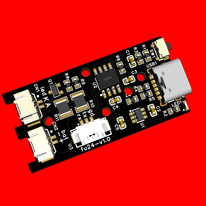
The microcontroller is an 8-pin SOIC package featuring a powerful 8051 core. The schematic connects a button, LED driver circuit, and UART on the right side. The UART is primarily used for downloading software. Typically, DIYing a small gadget takes me 1 to 2 months, but to finish before the New Year, I started pulling all-nighters to code. The programming is quite simple, with one input and one output. The input uses an external interrupt that is active low. From the code's switch statement, the LED has five operating modes: 0 off mode, 1 always on mode, 2 slow flash mode, 3 fast flash mode, and 4 alternating flash mode.
The Making Process
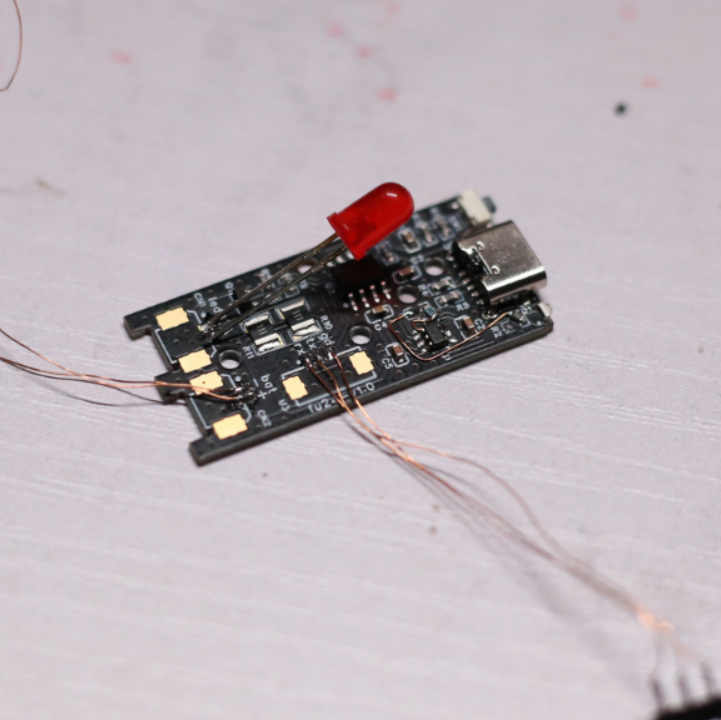
After compiling, I downloaded the HEX file to the microcontroller via the serial port. This was a prototype testing board, and some components, like the LED, were temporary. Once the prototype passed verification, I could continue to scale up the DIY project.
A "Fu" character sticker is a must for the New Year, so I decided to create it in a light-up PCB style. I designed the PCB directly without needing a schematic; the "Fu" character is the uncoated part, and the back has a window for light transmission, hence the name "light drawing." I made five samples, all in bright red, radiating festive vibes.
Assembly and Testing
On the 1mm thick PCB, the "Fu" character is prominently displayed in the center, surrounded by six traces. When placed under light, both the "Fu" character and the PCB traces illuminate, wishing everyone good fortune and smoke-free boards.
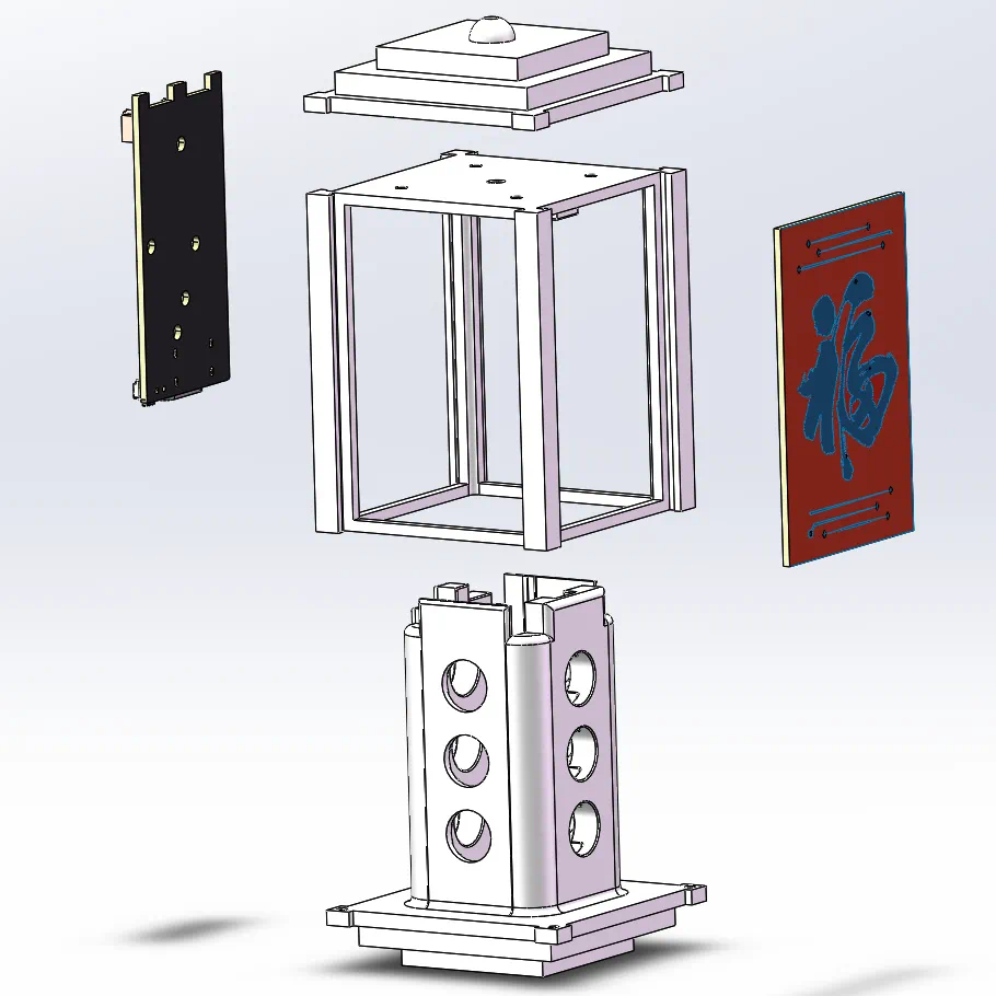
Once the circuit board was ready, I moved on to designing the structure diagram. The structure consists of three pieces, employing a nested and rail system to fit the circuit board inside. The colors of the components should be taken from the actual items, as depicted here for reference only.
Finally, my 3D-printed pieces arrived—three parts (top, middle, and bottom)—taking a full 10 days to print instead of the usual 3-4 days. I printed them using nylon material, which does not leak light, so I got to work quickly! I tested the compatibility of the "Fu" circuit board with the structural parts, and the assembly was smooth.
I used M1.2mm self-tapping screws, each 10mm long. To get 8 screws, I bought 1000 for just 4.24 yuan. I intentionally chose longer screws for better versatility; if they're too long, I can trim them with pliers, but if they're too short, it can be difficult to work with.
I assembled the top cover and the middle piece with screws, adding red cord before assembling. The control board, battery, and LED strip were soldered together, and the LED strip lit up. After placing them into the structure, the battery and control board fit snugly inside, while the 1.6mm thick yellow LED strip wrapped around the structure, secured with enameled wire.
Completion and Blessings
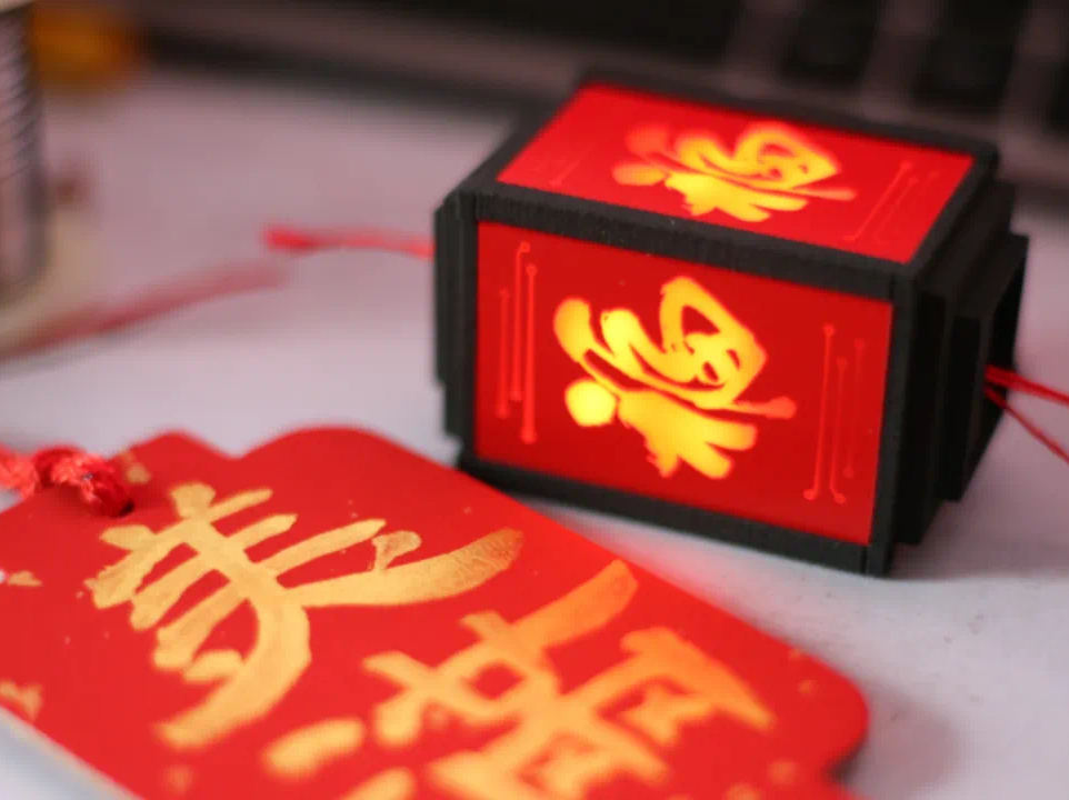
After assembling the three-piece structure and securing everything with self-tapping screws, the DIY project was complete. It features a striking red and black contrast. I turned on the always-on mode, illuminating the "Fu" character.
Here’s how it looks when hung up—the "Fu" character and PCB traces shine brightly. Wishing everyone abundant blessings and a joyful Spring Festival!