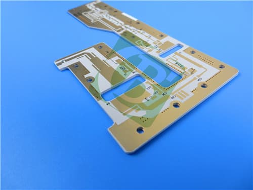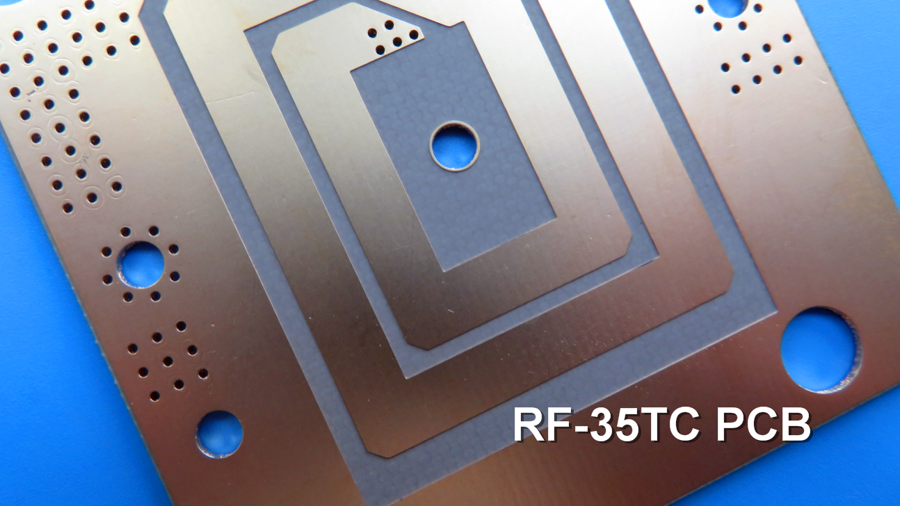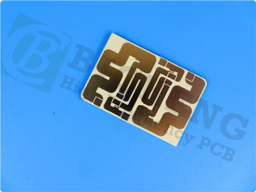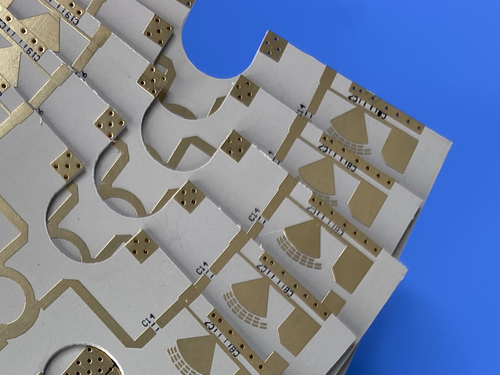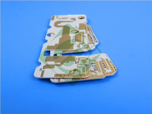
3 Layer RO3006 Hybrid RF PCB 0.86mm with Blind Vias for Microwave Applications1.Introduction Rogers RO3006 laminates are ceramic-filled PTFE composites engineered to deliver outstanding electrical and mechanical stability, making them ideal for commercial microwave and RF applications. These advanced circuit materials provide a consistent dielectric constant (Dk) across varying temperatures, eliminating the Dk shift commonly found in PTFE glass materials near room temperature. The dielectric constant can be arbitrarily selected within the range of 3 to 25 according to circuit requirements, and it is stable. Common dielectric constants include 3.0, 4.4, 6.0, 6.15, 9.2, 9.6, 9.8, 10.2, 11, 16, and 20. The dielectric loss is low, and the loss increases as the frequency increases, but the change is not significant within 10 GHz. The corresponding part numbers are TP300, TP440, TP600, TP615, TP920, TP960, TP980, TP1020 etc. 2.Key Features Ceramic-filled PTFE composite material 3.Benefits Uniform mechanical properties across a range of Dk values, ideal for multi-layer and hybrid PCB designs
4.PCB Construction Details
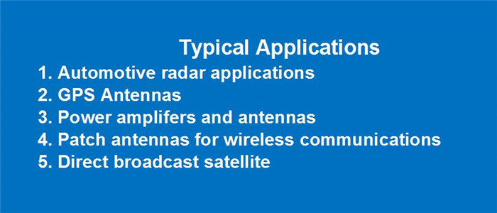
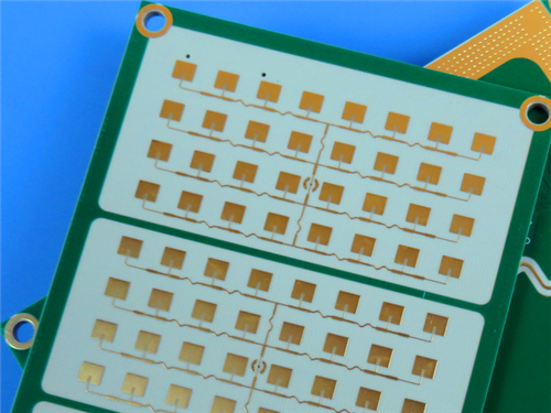
5.PCB Stackup (3-Layer Rigid Structure) Copper layer 1 - 35 μm 6.PCB Statistics: Components: 12 7.Typical Applications Automotive radar, GPS antennas, cellular communication systems, patch antennas, direct broadcast satellites, datalink systems, remote meter readers, and power backplanes. 8.Quality Assurance IPC-Class 2 compliant |
Get a Quick Quote
Fill in the form below and our engineers will reply within 24 hours with technical specifications and pricing for 3 Layer RO3006 Hybrid RF PCB 0.86mm with Blind Vias.