RF-10 High Frequency Printed Circuit Board: Low Loss, High DK PCB from Taconic
(Printed Circuit Boards are custom-made products, the picture and parameters shown are just for reference)
Product Overview
Introducing the RF-10 High Frequency Printed Circuit Board, a premium offering from Taconic. This innovative PCB features a composite of ceramic-filled PTFE and woven fiberglass, designed to meet the demands of high frequency applications. Key specifications include:
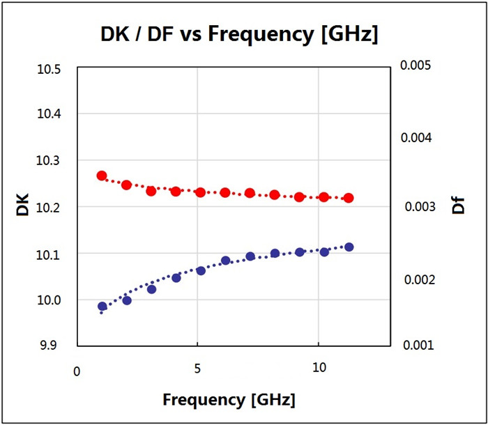
Dielectric Constant (DK): 10.2 at 10GHz
Dissipation Factor (DF): Low loss tangent of 0.0025 at 10GHz
Thickness Options: Available in 10mil, 20mil, and 60mil.
The RF-10 laminate is engineered for excellent dimensional stability and rigidity, making it ideal for multilayer circuits. Its unique composition allows for optimal insertion losses at higher frequencies, crucial where skin effect losses are significant.
Features and Benefits
1.Excellent Adhesion: Bonds effectively to smooth, low-profile copper.
2.Dimensional Stability: Maintains structural integrity across varying conditions.
3.Cost-Effective: High price/performance ratio for budget-conscious projects.
4.Thermal Conductivity: High thermal conductivity enhances thermal management.
5.Size Reduction: High DK allows for smaller RF circuit designs.
6.Low Loss: Remarkably low loss tangent at 10 GHz.
7.Minimal Expansion: Low X, Y, Z expansion for consistent performance.
8.Tight DK Tolerance: Achieves a DK of 10.2 ± 0.3.
Typical Applications
The RF-10 PCB is ideal for a variety of applications, including:
1.Aircraft Collision Avoidance Systems
2.GPS Antennas
3.Microstrip Patch Antennas
4.Passive Components (filters, couplers, power dividers)
5.Satellite Components
PCB Capability Table
| PCB Capability (RF-10) | |
| PCB Material: | Composites of Ceramic Filled PTFE and Woven Fiberglass |
| Designation: | RF-10 |
| Dielectric constant: | 10.2 |
| Dissipation Factor | 0.0025 10GHz |
| Layer count: | Double Sided PCB, Multilayer PCB, Hybrid PCB |
| Copper weight: | 0.5oz (17 µm), 1oz (35µm), 2oz (70µm) |
| PCB thickness: | 10mil (0.254mm), 20mil (0.508mm), 25mil (0.635mm), 60mil (1.524mm ), 125mil ( 3.175mm ) |
| PCB size: | ≤400mm X 500mm |
| Solder mask: | Green, Black, Blue, Yellow, Red etc. |
| Surface finish: | Bare copper, HASL, ENIG, Immersion silver, Immersion tin, OSP, Pure gold, ENEPIG etc.. |
RF-10 Typical Values Table
| RF-10 Typical Values | |||||
| Property | Test Method | Unit | Value | Unit | Value |
| Dk @ 10 GHz | IPC-650 2.5.5.5.1 Mod. | 10.2 ± 0.3 | 10.2 ± 0.3 | ||
| Df @ 10 GHz | IPC-650 2.5.5.5.1 Mod. | 0.0025 | 0.0025 | ||
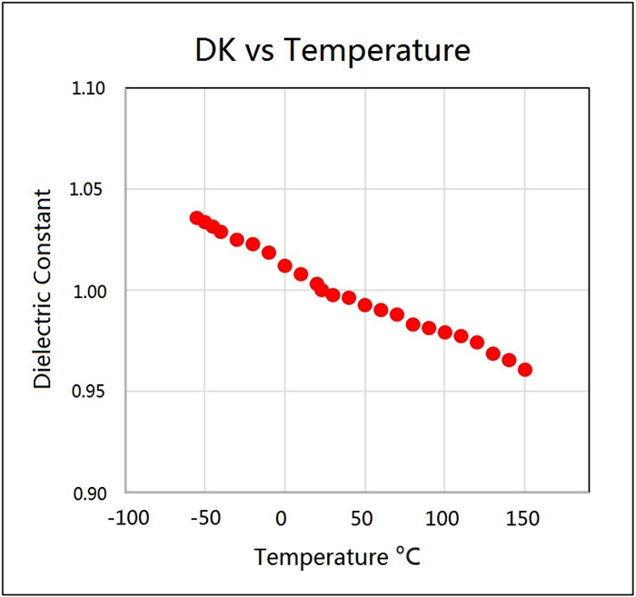
| TcK† (-55 to 150 °C) | IPC-650 2.5.5.6 | ppm/°C | -370 | ppm/°C | -370 |
| Moisture Absorption | IPC-650 2.6.2.1 | % | 0.08 | % | 0.08 |
| Peel Strength (1 oz. RT copper) | IPC-650 2.4.8 (solder) | lbs/in | 10 | N/mm | 1.7 |
| Volume Resistivity | IPC-650 2.5.17.1 | Mohm/cm | 6.0 x 10⁷ | Mohm/cm | 6.0 x 10⁷ |
| Surface Resistivity | IPC-650 2.5.17.1 | Mohm | 1.0 x 10⁸ | Mohm | 1.0 x 10⁸ |
| Flexural Strength (MD) | IPC - 650 - 2.4.4 | psi | 14,000 | N/mm2 | 96.53 |
| Flexural Strength (CD) | IPC - 650 - 2.4.4 | psi | 10,000 | N/mm2 | 68.95 |
| Tensile Strength (MD) | IPC - 650 - 2.4.19 | psi | 8,900 | N/mm2 | 62.57 |
| Tensile Strength (CD) | IPC - 650 - 2.4.19 | psi | 5,300 | N/mm2 | 37.26 |
| Dimensional Stability | IPC-650 2.4.39 (After Etch) | % (25 mil-MD) | -0.0032 | % (25 mil-CD) | -0.0239 |
| Dimensional Stability | IPC-650 2.4.39 (After Bake) | % (25 mil-MD) | -0.0215 | % (25 mil-CD) | -0.0529 |
| Dimensional Stability | IPC-650 2.4.39 (After Stress) | % (25 mil-MD) | -0.0301 | % (25 mil-CD) | -0.0653 |
| Dimensional Stability | IPC-650 2.4.39 (After Etch) | % (60 mil-MD) | -0.0027 | % (60 mil-CD) | -0.0142 |
| Dimensional Stability | IPC-650 2.4.39 (After Bake) | % (60 mil-MD) | -0.1500 | % (60 mil-CD) | -0.0326 |
| Dimensional Stability | IPC-650 2.4.39 (After Stress) | % (60 mil-MD) | -0.0167 | % (60 mil-CD) | -0.0377 |
| Density (Specific Gravity) | IPC-650-2.3.5 | g/cm3 | 2.77 | g/cm3 | 2.77 |
| Specific Heat | IPC-650-2.4.50 | J/g°C | 0.9 | J/g°C | 0.9 |
| Thermal Conductivity (Unclad) | IPC-650-2.4.50 | W/M*K | 0.85 | W/M*K | 0.85 |
| CTE (X -Y axis) (50 to 150 °C) | IPC-650 2.4.41 | ppm/°C | 16-20 | ppm/°C | 16-20 |
| CTE (Z axis) (50 to 150 °C) | IPC-650 2.4.41 | ppm/°C | 25 | ppm/°C | 25 |
| Flammability Rating | Internal | V-0 | V-0 | ||
.jpg)
Explore the RF-10 High Frequency Printed Circuit Board today for unparalleled performance in your RF applications! For any inquiries or to request a quote, please feel free to contact us.