Rogers 5880LZ High Frequency PCB - RT/duroid 5880LZ 50mil (1.27mm) 2-Layer Circuit Board with Immersion Gold
(Printed Circuit Boards are custom-made products, the picture and parameters shown are just for reference)
General Description
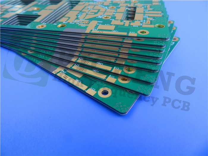
The Rogers 5880LZ High Frequency PCB is a double-layer circuit board designed for digital radio antenna applications. Built on Rogers RT/duroid 5880LZ laminates with a 50mil (1.27mm) substrate, it starts with 0.5oz copper and is finished with 1oz copper. The board features a green solder mask on the top side and immersion gold plating on the entire bottom layer. Manufactured in compliance with IPC Class 2 standards, all boards undergo 100% electrical testing (via flying probe or test fixture) before shipment to ensure quality and reliability.
PCB Specifications
| PCB SIZE | 75 x 60mm=1up |
| BOARD TYPE | Double sided PCB |
| Number of Layers | 2 layers |
| Surface Mount Components | YES |
| Through Hole Components | NO |
| LAYER STACKUP | copper ------- 17um(0.5 oz)+plate TOP layer |
| RT/duroid 5880LZ 1.27mm | |
| copper ------- 17um(0.5 oz) + plate BOT Layer | |
| TECHNOLOGY | |
| Minimum Trace and Space: | 4 mil / 4 mil |
| Minimum / Maximum Holes: | 0.4 mm / 3.0 mm |
| Number of Different Holes: | 7 |
| Number of Drill Holes: | 175 |
| Number of Milled Slots: | 0 |
| Number of Internal Cutouts: | 0 |
| Impedance Control: | no |
| Number of Gold finger: | 0 |
| BOARD MATERIAL | |
| Glass Epoxy: | RT/duroid 5880LZ 1.27mm |
| Final foil external: | 1.0 oz |
| Final foil internal: | N/A |
| Final height of PCB: | 1.4 mm ±0.1 |
| PLATING AND COATING | |
| Surface Finish | Immersion Gold, 51.8% |
| Solder Mask Apply To: | Top side |
| Solder Mask Color: | Green |
| Solder Mask Type: | LPI |
| CONTOUR/CUTTING | Routing |
| MARKING | |
| Side of Component Legend | N/A |
| Colour of Component Legend | N/A |
| Manufacturer Name or Logo: | N/A |
| VIA | Plated through hole(PTH), minimum size 0.4mm. |
| FLAMIBILITY RATING | 94V-0 |
| DIMENSION TOLERANCE | |
| Outline dimension: | 0.0059" |
| Board plating: | 0.0029" |
| Drill tolerance: | 0.002" |
| TEST | 100% Electrical Test prior shipment |
| TYPE OF ARTWORK TO BE SUPPLIED | email file, Gerber RS-274-X, PCBDOC etc |
| SERVICE AREA | Worldwide, Globally. |
Our Advantages
1.Comprehensive PCB Capabilities: Supporting research, development, sales, and marketing.
2. Certified Manufacturing: PCB products and processes are certified by authorized organizations.
3.Large Production Facility: 16,000㎡ workshop with a monthly output capacity of 30,000㎡.
4.High Production Volume: Capable of producing 8,000 types of PCBs per month.
5.Quick Turnaround: Fast CADCAM checking and free PCB quotations.
6.Flexible Ordering: No minimum order quantity (MOQ); single-piece orders are accepted.
7.Experienced Team: Over 19 years of expertise in high-frequency PCB manufacturing.
8.Prototype to Volume Production: Capable of handling both prototype and large-scale production.
9.Reliability: On-time delivery rate >98%, customer complaint rate <1%.
10.Quality Standards: IPC Class 2 and IPC Class 3 compliant.
Our PCB Capabilities (2022)
| Parameter | Value |
| Layer Counts | 1-32 |
| Substrate Material | RO4350B, RO4003C, RO4730G3, RO4360G2, RO4533, RO4534, RO4535, RO3003, RO3006, RO3010, RO3035, RO3203, RO3210; RT/Duriod 5880; RT/Duriod 5870, RT/Duriod 6002, RT/Duroid 6010, RT/duroid 6035HTC; RT/duroid 5880LZ; TMM3, TMM4, TMM6, TMM10, TMM10i, TMM13i, Kappa 438; TLF-35; RF-35TC, RF-60A, RF-60TC, RF-35A2, RF-45, RF-10, TRF-45; TLX-0, TLX-6, TLX-7, TLX-8; TLX-9, TLY-3, TLY-5; PTFE F4B (DK2.2 DK2.65 DK2.85 DK2.94, DK3.0, DK3.2, DK3.38, DK3.5, DK4.0, DK4.4, DK6.15, DK10.2); AD450, AD600, AD1000, TC350; Nelco N4000, N9350, N9240; FR-4 ( High Tg S1000-2M, TU-872 SLK, TU-768, IT-180A etc.), FR-4 High CTI>600V; Polyimide, PET; Metal Core etc. |
| Maximum Size | Flying test: 900*600mm, Fixture test 460*380mm, No test 1100*600mm |
| Board Outline Tolerance | ±0.0059" (0.15mm) |
| PCB Thickness | 0.0157" - 0.3937" (0.40mm--10.00mm) |
| Thickness Tolerance(T≥0.8mm) | ±8% |
| Thickness Tolerance(t<0.8mm) | ±10% |
| Insulation Layer Thickness | 0.00295" - 0.1969" (0.075mm--5.00mm) |
| Minimum Track | 0.003" (0.075mm) |
| Minimum Space | 0.003" (0.075mm) |
| Outer Copper Thickness | 35µm--350µm (1oz-10oz) |
| Inner Copper Thickness | 17µm--350µm (0.5oz - 10oz) |
| Drill Hole(Mechanical) | 0.0079" - 0.25" (0.2mm--6.35mm) |
| Finished Hole(Mechanical) | 0.0039"-0.248" (0.10mm--6.30mm) |
| DiameterTolerance(Mechanical) | 0.00295" (0.075mm) |
| Registration (Mechanical) | 0.00197" (0.05mm) |
| Aspect Ratio | 12:1 |
| Solder Mask Type | LPI |
| Min Soldermask Bridge | 0.00315" (0.08mm) |
| Min Soldermask Clearance | 0.00197" (0.05mm) |
| Plug via Diameter | 0.0098" - 0.0236" (0.25mm--0.60mm) |
| Impedance Control Tolerance | ±10% |
| Surface Finish | HASL,HASL LF,ENIG,Immersion Tin,Immersion Silver, OSP, Gold Finger, Pure gold plated etc. |
RO4533 Typical Values
| Property | Typical Value RT/duroid® 5880LZ | Direction | Units | Condition | Test Method |
| Dielectric Constant er,Process | 2.00 ± 0.04 | Z | 10 GHz/23°C | IPC-TM-650, 2.5.5.5 | |
| Dielectric Constant er,Design | 2.00 | Z | 8 GHz - 40 GHz | Differential Phase Length Method | |
| Dissipation Factor, tan | Typ: 0.0021 Max: 0.0027 | Z | 10GHz/23°C | IPC-TM-650, 2.5.5.5 | |
| Thermal Coefficient of Dielectric Constant, er | +20 | Z | ppm/°C | -50°C to 150°C 10GHz | IPC-TM-650, 2.5.5.5 |
| Volume Resistivity | 1.74 X 10^7 | Mohm•cm | C-96/35/90 | IPC-TM-650, 2.5.17.1 | |
| Surface Resistivity | 2.08 X 10^6 | Mohm | C-96/35/90 | IPC-TM-650, 2.5.17.1 | |
| Electrical Strength | 40 | KV | D48/50 | IPC-TM-650, 2.5.6 | |
| Dimensional Stability | -0.38 | X,Y | % | IPC-TM-650, 2.4.39A | |
| Moisture Absorption | 0.31 | % | 24 hours/23°C | IPC-TM-650, 2.6.2.1 | |
| Thermal Conductivity | 0.33 | Z | W/m/°K | 80°C | ASTM C518 |
| Coefficient of Thermal Expansion | 54, 47 40 | X,Y Z | ppm/°C | 0 to 150°C | IPC-TM-650, 2.4.41 |
| Outgassing | |||||
| TML | 0.01 | % | ASTM E-595 | ||
| CVCM | 0.01 | ||||
| WVR | 0.01 | ||||
| Density | 1.4 | gm/cm^3 | ASTM D792 | ||
| Copper Peel | >4.0 | pli | IPC-TM-650, 2.4.8 | ||
| Flammability | V-O | UL 94 | |||
| Lead-Free Process Compatible | YES | ||||