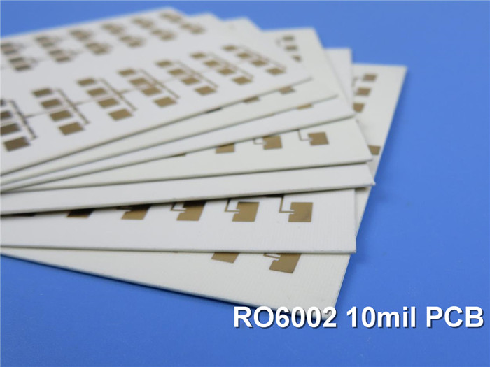
Rogers PCB Built on RT/Duroid 6002 10mil (0.254mm) DK2.94 with Immersion Gold for Phased Array Antennas
(Printed Circuit Boards are custom-made products; the images and specifications shown are for reference only.)
Overview of Rogers RT/Duroid 6002 Microwave Material
Rogers RT/Duroid 6002 is a pioneering microwave material, recognized for its low loss and low dielectric constant. This laminate offers exceptional electrical and mechanical properties, making it ideal for designing complex microwave structures that require both mechanical reliability and electrical stability.
Reliability Features
Thermal Stability and Performance:The thermal coefficient of dielectric constant for RT/Duroid 6002 remains impressively low across a temperature range of -55℃ to +150℃. This stability is crucial for designers of filters, oscillators, and delay lines, ensuring optimal performance in today's demanding applications.
Low Z-axis Coefficient of Thermal Expansion (CTE): This characteristic guarantees excellent reliability for plated through holes. RT/Duroid 6002 materials have successfully undergone temperature cycling (-55℃ to 125℃) for over 5000 cycles without a single via failure.
Dimensional Stability: Achieving excellent dimensional stability (0.2 to 0.5 mils/inch) is possible by aligning the X and Y coefficients of expansion with copper. This alignment often eliminates the need for double etching, ensuring tight positional tolerances.
Low Tensile Modulus: The low tensile modulus significantly minimizes stress on solder joints, allowing for constrained expansion of the laminate by a minimal amount of low CTE metal (6 ppm/℃), which enhances surface mount reliability.
Applications of RT/Duroid 6002
The unique properties of RT/Duroid 6002 make it particularly suitable for various applications, including:
1.Airborne radar systems
2.Beam forming networks
3.Commercial airline collision avoidance
4.Global positioning system antennas
5.Ground-based systems>
6.High-reliability complex multi-layer circuits
7.Phased array antennas
8.Power backplanes
PCB Specifications
Rogers RT/Duroid 6002 10mil 0.254mm High Frequency PCB for Phased Array Antennas |
|
PCB SIZE |
78 x 77 mm=1PCS |
BOARD TYPE |
Double sided PCB |
Number of Layers |
2 layers |
Surface Mount Components |
YES |
Through Hole Components |
NO |
LAYER STACKUP |
copper ------- 35um(1 oz)+plate TOP layer |
RT/duroid 6002 0.254mm |
|
copper ------- 35um(1 oz)+plate BOT layer |
|
TECHNOLOGY |
|
Minimum Trace and Space: |
10 mil / 10 mil |
Minimum / Maximum Holes: |
0.3 mm / 0.6 mm |
Number of Different Holes: |
1 |
Number of Drill Holes: |
2 |
Number of Milled Slots: |
0 |
Number of Internal Cutouts: |
0 |
Impedance Control: |
no |
Number of Gold finger: |
0 |
BOARD MATERIAL |
|
Glass Epoxy: |
RT/duroid 6002 0.254mm |
Final foil external: |
1 oz |
Final foil internal: |
1 oz |
Final height of PCB: |
0.3 mm ±0.1 |
PLATING AND COATING |
|
Surface Finish |
Immersion gold (51.3% ) 0.05µm over 3µm nickel |
Solder Mask Apply To: |
NO |
Solder Mask Color: |
NO |
Solder Mask Type: |
NO |
CONTOUR/CUTTING |
Routing |
MARKING |
|
Side of Component Legend |
N/A |
Colour of Component Legend |
N/A |
Manufacturer Name or Logo: |
N/A |
VIA |
Plated through hole(PTH), minimum size 0.3mm. |
FLAMIBILITY RATING |
UL 94-V0 Approval MIN. |
DIMENSION TOLERANCE |
|
Outline dimension: |
0.0059" |
Board plating: |
0.0029" |
Drill tolerance: |
0.002" |
TEST |
100% Electrical Test prior shipment |
TYPE OF ARTWORK TO BE SUPPLIED |
email file, Gerber RS-274-X, PCBDOC etc |
SERVICE AREA |
Worldwide, Globally. |
.jpg)
Conclusion
RT/Duroid 6002 PCBs are designed for a wide range of applications, particularly in environments requiring high performance and reliability. For inquiries or further information, please feel free to contact us.
Appendix: Data Sheet of RT/Duroid 6002
RT/duroid 6002 Typical Value |
|||||
Property |
RT/duroid 6002 |
Direction |
Units |
Condition |
Test Method |
Dielectric Constant,εProcess |
2.94±0.04 |
Z |
|
10 GHz/23℃ |
IPC-TM-650 2.5.5.5 |
Dielectric Constant,εDesign |
2.94 |
|
|
8GHz to 40 GHz |
Differential Phase Length Method |
Dissipation Factor,tanδ |
0.0012 |
Z |
|
10 GHz/23℃ |
IPC-TM-650 2.5.5.5 |
Thermal Coefficient of ε |
+12 |
Z |
ppm/℃ |
10 GHz 0℃-100℃ |
IPC-TM-650 2.5.5.5 |
Volume Resistivity |
106 |
Z |
Mohm.cm |
A |
ASTM D 257 |
Surface Resistivity |
107 |
Z |
Mohm |
A |
ASTM D 257 |
Tensile Modulus |
828(120) |
X,Y |
MPa(kpsi) |
23℃ |
ASTM D 638 |
Ultimate Stress |
6.9(1.0) |
X,Y |
MPa(kpsi) |
||
Ultimate Strain |
7.3 |
X,Y |
% |
||
Compressive Modulus |
2482(360) |
Z |
MPa(kpsi) |
|
ASTM D 638 |
Moisture Absorption |
0.02 |
|
% |
D48/50 |
IPC-TM-650 2.6.2.1 |
Thermal Conductivity |
0.6 |
|
W/m/k |
80℃ |
ASTM C518 |
Coefficient of Thermal Expansion |
16 |
X |
ppm/℃ |
23℃/50% RH |
IPC-TM-650 2.4.41 |
Td |
500 |
|
℃ TGA |
|
ASTM D 3850 |
Density |
2.1 |
|
gm/cm3 |
|
ASTM D 792 |
Specific Heat |
0.93(0.22) |
|
j/g/k |
|
Calculated |
Copper Peel |
8.9(1.6) |
|
Ibs/in.(N/mm) |
|
IPC-TM-650 2.4.8 |
Flammability |
V-0 |
|
|
|
UL 94 |
Lead-free Process Compatible |
Yes |
|
|
|
|