Rogers RO3003 High Frequency Printed Circuit Board Rogers DK3.0 GPS Antenna RF PCB 10mil, 20mil, 30mil and 60mil Thick Coating Immersion Gold
(PCB's are customized products, the pictures and parameters shown are for reference only)
Introduction to RO3003 High Frequency PCBs
The RO3003 high frequency circuit laminates are crafted from ceramic-filled PTFE composites, making them ideal for commercial microwave and RF applications. These materials deliver exceptional electrical performance and stable mechanical properties. Designers can confidently create multi-layer board designs without concerns about warpage or reliability issues.
Key Features and Applications
Features
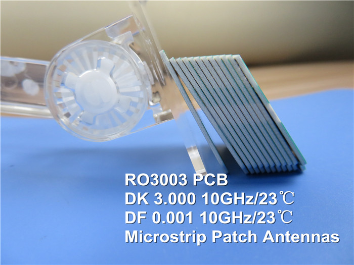
- 1.Low Dielectric Loss: With a dissipation factor (DF) of 0.001, RO3003 can be utilized in applications up to 77 GHz.
- 2.Stable Dielectric Constant: This material maintains a consistent dielectric constant across temperature and frequency, making it perfect for band pass filters, microstrip patch antennas, and voltage-controlled oscillators.
- 3.Excellent Mechanical Properties: The RO3003 offers reliable performance for stripline and multi-layer board constructions at varying temperatures.
- 4.Uniform Mechanical Properties: Suitable for epoxy glass multi-layer board hybrid designs.
- 5.Low In-Plane Expansion: The match to copper ensures more reliable surface-mounted assemblies, ideal for temperature-sensitive applications with excellent dimensional stability.
PCB Capabilities (RO3003)
PCB Material |
Ceramic-filled PTFE composite |
Designator |
RO3003 |
Dielectric Constant |
3.0 ±0.04 (process), 3.0 (design) |
Layer Count |
1 Layer, 2 Layer, Multi-layer, Hybrid PCB |
Copper Weight |
0.5oz (17 µm), 1oz (35µm), 2oz (70µm) |
PCB Thickness |
10mil (0.254mm), 20mil (0.508mm), 30mil (0.762mm), 60mil (1.524mm) |
PCB Size |
≤ 400mm x 500mm |
Solder Mask |
Available in Green, Black, Blue, Yellow, Red, etc. |
Surface Finish |
Options include Bare Copper, HASL, ENIG, OSP, etc. |
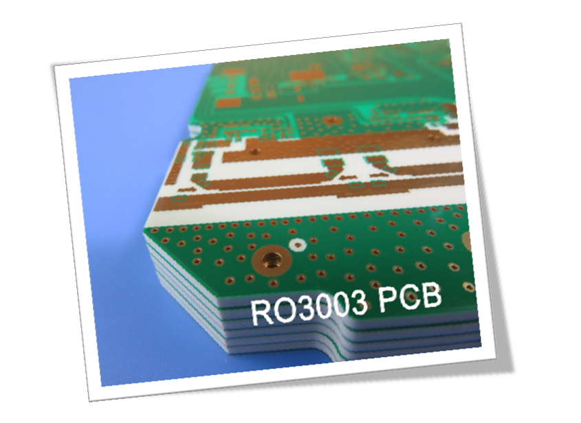
The RO3003 high frequency PCBs come in double-sided, multi-layer, and hybrid constructions, with copper weights ranging from 0.5oz to 2oz and thicknesses from 0.3mm to 1.6mm. The maximum size available is 400mm x 500mm, with surface finishes including bare copper, hot air leveling, and immersion gold.
Typical Applications
- Automotive radar systems
- GPS antennas
- Power amplifiers and antennas
- Patch antennas for wireless communication
- Direct broadcast satellite systems
The basic color of the RO3003 PCB is white. Its manufacturing process is similar to standard PTFE PCBs, making it suitable for high-volume production, thus providing a competitive edge in the market.
Conclusion
If you have any questions or need further information, please don’t hesitate to contact us.
Thank you for reading!
Appendix: Data Sheet of RO3003
RO3003 Typical Value |
|||||
Property |
RO3003 |
Direction |
Units |
Condition |
Test Method |
Electrical Properties |
|
|
|
|
|
Dielectric Constant,εProcess |
3.0±0.04 |
Z |
|
10 GHz/23℃ |
IPC-TM-650 2.5.5.5 Clamped Stripline |
Dielectric Constant,εDesign |
3 |
Z |
|
8GHz to 40 GHz |
Differential Phase Length Method |
Dissipation Factor,tanδ |
0.001 |
Z |
|
10 GHz/23℃ |
IPC-TM-650 2.5.5.5 |
Thermal Coefficient of ε |
-3 |
Z |
ppm/℃ |
10 GHz -50℃to 150℃ |
IPC-TM-650 2.5.5.5 |
Volume Resistivity |
107 |
|
MΩ.cm |
COND A |
IPC 2.5.17.1 |
Surface Resistivity |
107 |
|
MΩ |
COND A |
IPC 2.5.17.1 |
Thermal Properties |
|
|
|
|
|
Td |
500 |
|
℃ TGA |
|
ASTM D 3850 |
Coefficient of Thermal Expansion |
17 |
X |
ppm/℃ |
23℃/50% RH |
IPC-TM-650 2.4.4.1 |
Thermal Conductivity |
0.5 |
|
W/M/K |
50℃ |
ASTM D 5470 |
Mechanical Properties |
|
|
|
|
|
Copper Peel Stength |
12.7 |
|
Ib/in. |
1oz,EDC After Solder Float |
IPC-TM 2.4.8 |
Young's Modulus |
930 |
X |
MPa |
23℃ |
ASTM D 638 |
Dimensional Stability |
-0.06 |
X |
mm/m |
COND A |
IPC-TM-650 2.2.4 |
Physical Properties |
|
|
|
|
|
Flammability |
V-0 |
|
|
|
UL 94 |
Moisture Absorption |
0.04 |
|
% |
D48/50 |
IPC-TM-650 2.6.2.1 |
Density |
2.1 |
|
gm/cm3 |
23℃ |
ASTM D 792 |
Specific Heat |
0.9 |
|
j/g/k |
|
Calculated |
Lead-free Process Compatible |
Yes |
|
|
|
|