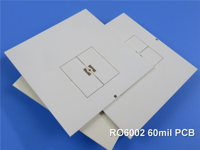
Rogers RT/Duroid 6002 60mil 1.524mm DK2.94 with Immersion Gold for Commercial Airline Collision Avoidance
(Printed Circuit Boards are custom-made products, the picture and parameters shown are just for reference)
Rogers HF PCB built on RT/Duroid 6002 with a thickness of 60mil (1.524mm) and a dielectric constant (DK) of 2.94, features immersion gold finishing, specifically designed for commercial airline collision avoidance systems.
Key Characteristics
1.Low Loss and Dielectric Constant:RT/Duroid 6002 offers superior electrical and mechanical properties, essential for complex microwave structures that require reliability and stability.
2.Thermal Stability:The thermal coefficient of dielectric constant remains stable from -55℃ to +150℃, providing essential electrical stability for filters, oscillators, and delay lines under demanding conditions.
3.Reliable Plated Through Holes:A low Z-axis coefficient of thermal expansion (CTE) ensures excellent reliability, with over 5000 temperature cycles (-55℃ to 125℃) completed without any via failures.
4.Dimensional Stability:Achieves exceptional dimensional stability (0.2 to 0.5 mils/inch) by matching the expansion coefficients of the laminate and copper, often eliminating the need for double etching.
5.Reduced Stress on Solder Joints:The low tensile modulus minimizes stress on solder joints, enhancing surface mount reliability by constraining the laminate's expansion with low CTE metal (6 ppm/℃).
Applications
Applications particularly suited to the unique properties of RT/duroid 6002 material include flat and non-planar structures such antennas, complex mutli-layer circuits with inter-layer connections, and microwave circuits for aerospace designs in hostile environments.
RT/Duroid 6002 is particularly suited for:
*Airborne radar systems
*Beam forming networks
*Commercial airline collision avoidance
*GPS antennas
*Ground-based systems
*High-reliability multi-layer circuits
*Phased array antennas
*Power backplanes
PCB Applications
The unique properties of RT/Duroid 6002 make it ideal for various applications, including flat and non-planar structures, antennas, complex multi-layer circuits with inter-layer connections, and microwave circuits designed for aerospace applications in challenging environments.
Typical Applications Include:
1.Airborne Radar Systems
2.Beam Forming Networks
3.Commercial Airline Collision Avoidance Systems
4.Global Positioning System (GPS) Antennas
5.Ground-Based Systems
6.High-Reliability Complex Multi-Layer Circuits
7.Phased Array Antennas
8.Power Backplanes
PCB Specifications
Rogers RT/Duroid 6002 60mil 1.524mm High Frequency PCB for Commercial Airline Collision Avoidance |
|
PCB SIZE |
99 x 99 mm=1PCS |
BOARD TYPE |
Double sided PCB |
Number of Layers |
2 layers |
Surface Mount Components |
YES |
Through Hole Components |
NO |
LAYER STACKUP |
copper ------- 18um(0.5 oz)+plate TOP layer |
RT/duroid 1.524mm |
|
copper ------- 18um(0.5 oz)+plate BOT layer |
|
TECHNOLOGY |
|
Minimum Trace and Space: |
4 mil / 4 mil |
Minimum / Maximum Holes: |
0.3 mm / 2.0mm |
Number of Different Holes: |
1 |
Number of Drill Holes: |
3 |
Number of Milled Slots: |
0 |
Number of Internal Cutouts: |
0 |
Impedance Control: |
no |
Number of Gold finger: |
0 |
BOARD MATERIAL |
|
Glass Epoxy: |
RT/duroid 1.524mm |
Final foil external: |
1 oz |
Final foil internal: |
1 oz |
Final height of PCB: |
1.6 mm ±0.16 |
PLATING AND COATING |
|
Surface Finish |
Immersion gold (51.3% ) 0.05µm over 3µm nickel |
Solder Mask Apply To: |
NO |
Solder Mask Color: |
NO |
Solder Mask Type: |
NO |
CONTOUR/CUTTING |
Routing |
MARKING |
|
Side of Component Legend |
NO |
Colour of Component Legend |
NO |
Manufacturer Name or Logo: |
NO |
VIA |
Plated through hole(PTH), minimum size 0.3mm. |
FLAMIBILITY RATING |
UL 94-V0 Approval MIN. |
DIMENSION TOLERANCE |
|
Outline dimension: |
0.0059" |
Board plating: |
0.0029" |
Drill tolerance: |
0.002" |
TEST |
100% Electrical Test prior shipment |
TYPE OF ARTWORK TO BE SUPPLIED |
email file, Gerber RS-274-X, PCBDOC etc |
SERVICE AREA |
Worldwide, Globally. |
Data Sheet of Rogers 6002 (RT/Duroid 6002)
RT/duroid 6002 Typical Value |
|||||
Property |
RT/duroid 6002 |
Direction |
Units |
Condition |
Test Method |
Dielectric Constant,εProcess |
2.94±0.04 |
Z |
|
10 GHz/23℃ |
IPC-TM-650 2.5.5.5 |
Dielectric Constant,εDesign |
2.94 |
|
|
8GHz to 40 GHz |
Differential Phase Length Method |
Dissipation Factor,tanδ |
0.0012 |
Z |
|
10 GHz/23℃ |
IPC-TM-650 2.5.5.5 |
Thermal Coefficient of ε |
+12 |
Z |
ppm/℃ |
10 GHz 0℃-100℃ |
IPC-TM-650 2.5.5.5 |
Volume Resistivity |
106 |
Z |
Mohm.cm |
A |
ASTM D 257 |
Surface Resistivity |
107 |
Z |
Mohm |
A |
ASTM D 257 |
Tensile Modulus |
828(120) |
X,Y |
MPa(kpsi) |
23℃ |
ASTM D 638 |
Ultimate Stress |
6.9(1.0) |
X,Y |
MPa(kpsi) |
||
Ultimate Strain |
7.3 |
X,Y |
% |
||
Compressive Modulus |
2482(360) |
Z |
MPa(kpsi) |
|
ASTM D 638 |
Moisture Absorption |
0.02 |
|
% |
D48/50 |
IPC-TM-650 2.6.2.1 |
Thermal Conductivity |
0.6 |
|
W/m/k |
80℃ |
ASTM C518 |
Coefficient of Thermal Expansion |
16 |
X |
ppm/℃ |
23℃/50% RH |
IPC-TM-650 2.4.41 |
Td |
500 |
|
℃ TGA |
|
ASTM D 3850 |
Density |
2.1 |
|
gm/cm3 |
|
ASTM D 792 |
Specific Heat |
0.93(0.22) |
|
j/g/k |
|
Calculated |
Copper Peel |
8.9(1.6) |
|
Ibs/in.(N/mm) |
|
IPC-TM-650 2.4.8 |
Flammability |
V-0 |
|
|
|
UL 94 |
Lead-free Process Compatible |
Yes |
|
|
|
|