| |
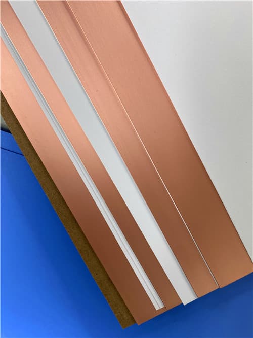
Wangling F4BM220 DK2.20 Df0.001 (0.1-12.0mm) Copper Clad Laminate
Brief Introduction
F4BM220 is a PTFE and fiberglass composite laminate offering a dielectric constant of 2.20, designed for RF and microwave printed circuit boards. It provides excellent electrical performance, thermal stability, and mechanical reliability for high-frequency electronic applications.
Technical Features & Benefits
- Stable Dielectric Constant: Dk = 2.20 ±0.04 at 10 GHz, ensuring consistent electrical performance across batches.
- Low Loss Performance: Loss tangent of 0.001 at 10 GHz, 0.0014 at 20 GHz, minimizing signal attenuation.
- Low Thermal Expansion: CTE in XY direction: 25–34 ppm/°C, Z direction: 240 ppm/°C, ensuring excellent dimensional stability.
- High Insulation Resistance: Volume resistivity ≥6×10⁶ MΩ·cm for reliable electrical isolation.
- Good Thermal Conductivity: 0.24 W/(m·K) in Z direction for improved heat dissipation in power applications.
.jpg)
Typical Properties: F4BM 220
| Property |
Test Condition |
Unit |
F4BM220 |
| Dielectric Constant (Typ.) | 10 GHz | – | 2.20 |
| Dk Tolerance | – | – | ±0.04 |
| Loss Tangent (Typ.) | 10 GHz | – | 0.001 |
| 20 GHz | – | 0.0014 |
| TC of Dk | –55°C to 150°C | ppm/°C | –142 |
| Peel Strength (1 oz) | ED Copper | N/mm | >1.8 |
| Volume Resistivity | Ambient | MΩ·cm | ≥6×10⁶ |
| Surface Resistivity | Ambient | MΩ | ≥1×10⁶ |
| Dielectric Strength (Z) | 5 kV, 500 V/s | kV/mm | >23 |
| Breakdown Voltage (XY) | 5 kV, 500 V/s | kV | >30 |
| CTE (XY) | –55°C to 288°C | ppm/°C | 25–34 |
| CTE (Z) | –55°C to 288°C | ppm/°C | 240 |
| Water Absorption | 20±2°C, 24 h | % | ≤0.08 |
| Density | Ambient | g/cm³ | 2.18 |
| Thermal Conductivity (Z) | Z-direction | W/(m·K) | 0.24 |
| Flammability | – | UL 94 | V-0 |
Application Areas
- RF and microwave circuits – High-frequency signal processing.
- Phase shifters and passive components – Precision RF control elements.
- Power dividers and couplers – Signal distribution and combining.
- Antenna feed networks – Feeding structures for antenna arrays.
- Satellite communication systems – Reliable performance in space applications.
Available Configurations
- Copper Foil: ED copper, various weights available.
- Standard Sizes: 460×610 mm, 500×600 mm, 914×1220 mm, etc.
- Thickness Options: 0.1 mm to 12.0 mm with specified tolerances.
- Metal Substrate Options: Available with aluminum or copper backing (F4BM220–AL/CU).
|
|
.jpg)
.jpg)
.jpg)
.jpg)
.png)
.jpg)
.jpg)
