F4BM220 High Frequency PCB DK 2.2 PTFE PCB with 3.0mm Thick 1oz Copper and HASL Lead Free
(Printed Circuit Boards are custom-made products, the pictures and parameters shown are just for reference)
Hello everyone,
Today, we discuss the F4BM220 high frequency circuit board, featuring a thickness of 3.0mm.
The F4BM series laminates are crafted through a precise formulation and pressing of fiberglass cloth, polytetrafluoroethylene (PTFE) resin, and PTFE film. This design enhances electrical performance compared to standard F4B materials. Key improvements include a broader range of dielectric constants, reduced dielectric loss, higher insulation resistance, and enhanced stability, making it a viable alternative to similar foreign products.
PCB Specifications
Specification |
Details |
Layer Count |
Double-sided |
Base Material |
F4BM220 (DK 2.2) |
Dimensions |
61 x 62 mm |
Finished Thickness |
3.0 mm ±10% |
Finished Copper Weight |
1 oz |
SMOBC |
No |
Surface Finish |
HASL Lead Free |
The F4BM220 PCB is a double-sided board with a substrate of F4BM220, featuring a dielectric constant of 2.2. It measures 61mm in length and 62mm in width, with a finished thickness of 3.0mm and a copper weight of 1.0 oz. This board does not include a solder mask or silkscreen, and it utilizes HASL as the surface finish.
Stack-Up Details
The top and bottom layers are finished with 1 oz copper. The F4BM220 dielectric material is sandwiched between the two layers of copper, maintaining a dielectric constant of 2.2 within the 3.0mm thickness.
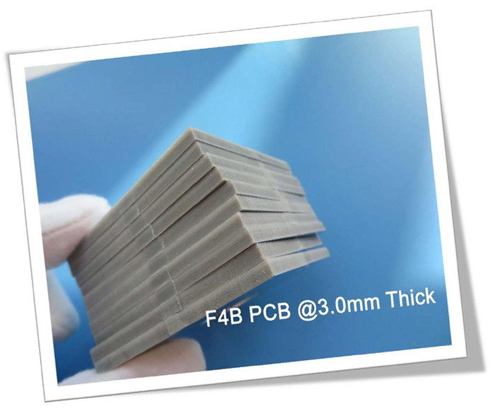
This is the photo of this board. The basic colour of F4BM220 PCB is brown.
Our PCB Capability (F4BM)| Specification
PCB Capability (F4BM) |
|||
PCB Material: |
PTFE glass fiber cloth copper clad laminates |
||
Designation (F4BM ) |
F4BM |
DK (10GHz) |
DF (10 GHz) |
F4BM217 |
2.17±0.04 |
0.0010 |
|
F4BM220 |
2.20±0.04 |
0.0010 |
|
F4BM233 |
2.33±0.04 |
0.0011 |
|
F4BM245 |
2.45±0.05 |
0.0012 |
|
F4BM255 |
2.55±0.05 |
0.0013 |
|
F4BM265 |
2.65±0.05 |
0.0013 |
|
F4BM275 |
2.75±0.05 |
0.0015 |
|
F4BM294 |
2.94±0.06 |
0.0016 |
|
F4BM300 |
3.00±0.06 |
0.0017 |
|
Layer count: |
Single Sided, Double Sided PCB, Multilayer PCB, Hybrid PCB |
||
Copper weight: |
0.5oz (17 µm), 1oz (35µm), 2oz (70µm) |
||
Dielectric thickness (or overall thickness) |
0.127mm (dielectric), 0.2mm, 0.25mm, 0.5mm, 0.508mm, 0.762mm, 0.8mm, 1.0mm, 1.5mm, 1.524mm, 1.575mm, 2.0mm, 2.5mm, 3.0mm, 4.0mm, 5.0mm, 6.0mm, 8.0mm, 10.0mm, 12.0mm |
||
PCB size: |
≤400mm X 500mm |
||
Solder mask: |
Green, Black, Blue, Yellow, Red etc. |
||
Surface finish: |
Bare copper, HASL, ENIG, Immersion silver, Immersion tin, OSP, Pure gold, ENEPIG etc.. |
||
The dielectric constant of F4BM material is wide, ranging 2.17 to 3.0. Board thickness ranges 0.13mm to 12.0mm. We offer services for prototypes, small batches, and mass production.
If you have any questions, please feel free to contact us.Thank you for your attention.
Appendix: Data Sheet (F4BM)
Product Technical Parameters |
Product Model & Data Sheet |
|||||||||||
Product Features |
Test Conditions |
Unit |
F4BM217 |
F4BM220 |
F4BM233 |
F4BM245 |
F4BM255 |
F4BM265 |
F4BM275 |
F4BM294 |
F4BM300 |
|
Dielectric Constant (Typical) |
10GHz |
/ |
2.17 |
2.2 |
2.33 |
2.45 |
2.55 |
2.65 |
2.75 |
2.94 |
3.0 |
|
Dielectric Constant Tolerance |
/ |
/ |
±0.04 |
±0.04 |
±0.04 |
±0.05 |
±0.05 |
±0.05 |
±0.05 |
±0.06 |
±0.06 |
|
Loss Tangent (Typical) |
10GHz |
/ |
0.001 |
0.001 |
0.0011 |
0.0012 |
0.0013 |
0.0013 |
0.0015 |
0.0016 |
0.0017 |
|
20GHz |
/ |
0.0014 |
0.0014 |
0.0015 |
0.0017 |
0.0018 |
0.0019 |
0.0021 |
0.0023 |
0.0025 |
||
Dielectric Constant Temperature Coefficient |
-55ºC~150ºC |
PPM/℃ |
-150 |
-142 |
-130 |
-120 |
-110 |
-100 |
-92 |
-85 |
-80 |
|
Peel Strength |
1 OZ F4BM |
N/mm |
>1.8 |
>1.8 |
>1.8 |
>1.8 |
>1.8 |
>1.8 |
>1.8 |
>1.8 |
>1.8 |
|
1 OZ F4BME |
N/mm |
>1.6 |
>1.6 |
>1.6 |
>1.6 |
>1.6 |
>1.6 |
>1.6 |
>1.6 |
>1.6 |
||
Volume Resistivity |
Standard Condition |
MΩ.cm |
≥6×10^6 |
≥6×10^6 |
≥6×10^6 |
≥6×10^6 |
≥6×10^6 |
≥6×10^6 |
≥6×10^6 |
≥6×10^6 |
≥6×10^6 |
|
Surface Resistivity |
Standard Condition |
MΩ |
≥1×10^6 |
≥1×10^6 |
≥1×10^6 |
≥1×10^6 |
≥1×10^6 |
≥1×10^6 |
≥1×10^6 |
≥1×10^6 |
≥1×10^6 |
|
Electrical Strength (Z direction) |
5KW,500V/s |
KV/mm |
>23 |
>23 |
>23 |
>25 |
>25 |
>25 |
>28 |
>30 |
>30 |
|
Breakdown Voltage (XY direction) |
5KW,500V/s |
KV |
>30 |
>30 |
>32 |
>32 |
>34 |
>34 |
>35 |
>36 |
>36 |
|
Coefficientof Thermal Expansion |
XY direction |
-55 º~288ºC |
ppm/ºC |
25, 34 |
25, 34 |
22, 30 |
20, 25 |
16, 21 |
14, 17 |
14, 16 |
12, 15 |
12, 15 |
Z direction |
-55 º~288ºC |
ppm/ºC |
240 |
240 |
205 |
187 |
173 |
142 |
112 |
98 |
95 |
|
Thermal Stress |
260℃, 10s,3 times |
No delamination |
No delamination |
No delamination |
No delamination |
No delamination |
No delamination |
No delamination |
No delamination |
No delamination |
||
Water Absorption |
20±2℃, 24 hours |
% |
≤0.08 |
≤0.08 |
≤0.08 |
≤0.08 |
≤0.08 |
≤0.08 |
≤0.08 |
≤0.08 |
≤0.08 |
|
Density |
Room Temperature |
g/cm3 |
2.17 |
2.18 |
2.20 |
2.22 |
2.25 |
2.25 |
2.28 |
2.29 |
2.29 |
|
Long-Term Operating Temperature |
High-Low Temperature Chamber |
℃ |
-55~+260 |
-55~+260 |
-55~+260 |
-55~+260 |
-55~+260 |
-55~+260 |
-55~+260 |
-55~+260 |
-55~+260 |
|
Thermal Conductivity |
Z direction |
W/(M.K) |
0.24 |
0.24 |
0.28 |
0.30 |
0.33 |
0.36 |
0.38 |
0.41 |
0.42 |
|
PIM |
Only applicable to F4BME |
dBc |
≤-159 |
≤-159 |
≤-159 |
≤-159 |
≤-159 |
≤-159 |
≤-159 |
≤-159 |
≤-159 |
|
Flammability |
/ |
UL-94 |
V-0 |
V-0 |
V-0 |
V-0 |
V-0 |
V-0 |
V-0 |
V-0 |
V-0 |
|
Material Composition |
/ |
/ |
PTFE, Fiberglass Cloth |
|||||||||