6-Layer S1000-2M HDI PCB with HASL and 90 Ohm Impedance Control
(All PCBs are custom-manufactured. Reference images and parameters may vary based on your design requirements.)
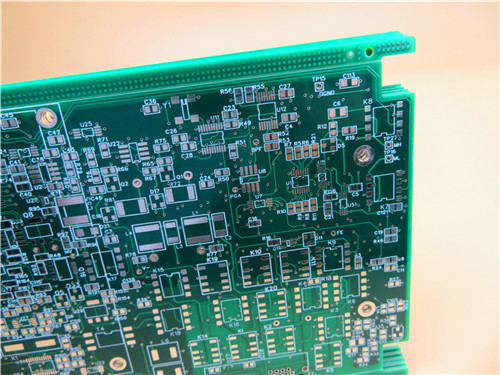
Brief Introduction
This 6-layer printed circuit board utilizes high-Tg S1000-2M material, designed for differential impedance control on layer 3 (6 mil/7 mil and 6 mil/10 mil) and layer 4 (7 mil/7 mil and 6 mil/7 mil track/gap). Each layer is plated with 1 oz of copper and coated with hot air solder leveling (HASL) along with a green solder mask. The board features a high-density interconnection (HDI) configuration, incorporating blind vias from the top side to inner layer 4 and buried vias from inner layer 3 to inner layer 4. Fabricated according to IPC-class 2 standards, it is supplied with V-cut, with 25 boards packed for shipment.
PCB Parameters
| PCB Parameters | ||||
| Item | Description | Requirement | Actual | Result |
| 1. Laminate | Material Type | FR-4 S1000-2M | FR-4 S1000-2M | ACC |
| Tg | 170℃ | 170℃ | ACC | |
| Supplier | SHENGYI | SHENGYI | ACC | |
| Thickness | 1.6±10% mm | 1.63-1.68mm | ACC | |
| 2.Plating thickness | Hole Wall | ≥25µm | 30.17µm | ACC |
| Outer copper | 35µm | 41.09µm | ACC | |
| Inner Copper | 30µm | 33.69µm | ACC | |
| 3.Solder mask | Material Type | TAIYO/ PSR-2000GT600D | TAIYO/ PSR-2000GT600D | ACC |
| Color | Green | Green | ACC | |
| Rigidity (Pencil Test) | ≥4H or above | 5H | ACC | |
| S/M Thickness | ≥10 µm | 20.11µm | ACC | |
| Location | Both Sides | Both Sides | ACC | |
| 4. Component Mark | Material Type | TAIYO/ IJR-4000 MW300 | IJR-4000 MW300 | ACC |
| Color | White | White | ACC | |
| Location | C/S | C/S | ACC | |
| 5.Vias | Through holes | Yes | L1-L6 | ACC |
| Blind vias | Yes | L1-L5 | ACC | |
| Buried vias | Yes | L4-L5 | ACC | |
| 6. Identification | UL Mark | YES | YES | ACC |
| Date Code | WWYY | 0421 | ACC | |
| Mark Location | Solder Side | Solder Side | ACC | |
| 7. Surface Finish | Method | HASL Lead Free | HASL Lead Free | ACC |
| Tin Thickness | 3-6µm | 4.06µm | ACC | |
| Nickel Thickness | ||||
| Gold Thickness | ||||
| 8. Normativeness | RoHS | Directive 2015/863/EU | OK | ACC |
| REACH | Directive 1907 /2006 | OK | ACC | |
| 9.Annular Ring | Min. Line Width (mil) | 6mil | 5.8mil | ACC |
| Min. Spacing (mil) | 5mil | 5.2mil | ACC | |
| 10.V-groove | Angle | 30° | 30° | ACC |
| Residual thickness | 0.5mm | 0.5mm | ACC | |
| 11. Beveling | Angle | |||
| Height | ||||
| 12. Function | Electrical Test | 100% PASS | 100% PASS | ACC |
| 13. Appearance | IPC Class Level | IPC-A-600J &6012D Class 2 | IPC-A-600J &6012D Class 2 | ACC |
| Visual Inspection | IPC-A-600J &6012D Class 2 | IPC-A-600J &6012D Class 2 | ACC | |
| Warp and Twist | ≦0.7% | 0.21% | ACC | |
| 14. Reliability Test | Tape Test | No Peeling | OK | ACC |
| Solvent Test | No Peeling | OK | ACC | |
| Solderability Test | 265 ±5℃ | OK | ACC | |
| Thermal Stress Test | 288 ±5℃ | OK | ACC | |
| Ionic Contamination Test | ≦ 1.56 µg/c㎡ | 0.56µg/c㎡ | ACC |
Applications
Computers: Suitable for high-performance computing systems.
Communications: Ideal for telecommunications devices.
Automotive Electronics: Meets the demands of automotive applications.
Hole Diameter Measurement (Unit: mm),Tolerance: PTH±0.075; NPTH±0.05
| Hole Code | PTH | Required | Actual value | Result | |||
| 1 | Y | 0.375 | 0.375 | 0.400 | 0.400 | 0.375 | ACC |
| 2 | Y | 0.500 | 0.500 | 0.550 | 0.525 | 0.525 | ACC |
| 3 | Y | 0.7*2.4 | 0.7*2.4 | 0.7*2.41 | 0.69*2.4 | 0.7*2.4 | ACC |
| 4 | Y | 0.625 | 0.625 | 0.600 | 0.625 | 0.600 | ACC |
| 5 | Y | 0.725 | 0.725 | 0.725 | 0.750 | 0.725 | ACC |
| 6 | Y | 0.900 | 0.925 | 0.900 | 0.900 | 0.900 | ACC |
| 7 | Y | 1.000 | 1.000 | 0.950 | 0.975 | 1.000 | ACC |
| 8 | N | 1.050 | 1.050 | 1.050 | 1.075 | 1.050 | ACC |
| 9 | Y | 1.300 | 1.300 | 1.300 | 1.325 | 1.325 | ACC |
| 10 | Y | 1.350 | 1.350 | 1.325 | 1.350 | 1.325 | ACC |
| 11 | Y | 1.575 | 1.575 | 1.600 | 1.600 | 1.575 | ACC |
| 12 | Y | 1.650 | 1.650 | 1.700 | 1.675 | 1.675 | ACC |
| 13 | Y | 1.700 | 1.700 | 1.750 | 1.725 | 1.725 | ACC |
| 14 | Y | 3.250 | 3.250 | 3.250 | 3.275 | 3.250 | ACC |
| 15 | Y | 3.450 | 3.450 | 3.400 | 3.425 | 3.450 | ACC |
| 16 | Y | 0.7*2.6 | 0.7*259 | 0.7*2.61 | 0.69*2.6 | 0.7*2.59 | ACC |
Impedance Test Report
| Sample NO. | Layer | Line Width(mil)±10% | Line Space (mil)±10% | Impedance Type | Required Value (ohm) | Tolerance | Actual Value | Result | |
| Single End | Differential | ||||||||
| 1 | L3 | 6.000 | 7.000 | V | 90.00 | ±10% | 93.59 | ACC | |
| L3 | 6.000 | 10.000 | V | 100.00 | ±10% | 102.33 | ACC | ||
| L4 | 7.000 | 7.000 | V | 90.00 | ±10% | 88.99 | ACC | ||
| L4 | 6.000 | 7.000 | V | 90.00 | ±10% | 90.76 | ACC | ||
