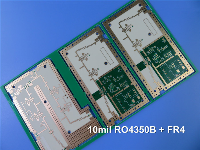
RO3003™ + FR4 Hybrid 4-Layer PCB with Countersink Slot L2-L4 for Microwave, Radar & Automotive Applications
(Note: Printed Circuit Boards are custom-made. Images and parameters are for reference only.)
Introduction to RO3003™ Hybrid High Frequency PCB
Rogers RO3003 is a ceramic-filled PTFE composite laminate with a dielectric constant (Dk) of 3.00 ± 0.04 at 10GHz and an extremely low dissipation factor (Df) of 0.0010, offering exceptional high-frequency performance. This material is ideal for commercial microwave and RF applications, including automotive radar (up to 77GHz), band pass filters, microstrip patch antennas, and voltage-controlled oscillators.
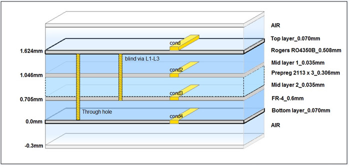
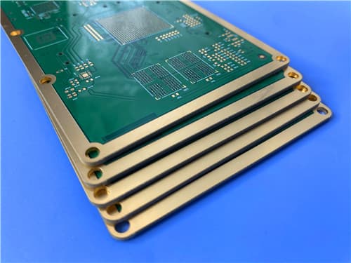
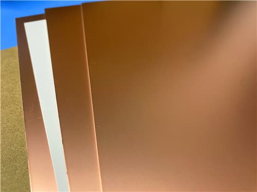
This 4-layer hybrid board combines a 10mil (0.254mm) RO3003™ core with a 0.15mm FR4 TG170°C core, bonded together with prepreg. The stackup is finished with 1oz copper on outer layers and 0.5oz on inner layers. The board features a countersink slot from L2 to L4 with no plating required. With 1oz copper on all layers and ENIG surface finish, this PCB meets the demands of high-reliability microwave and RF applications.
Key Features of RO3003™ Hybrid PCB
Dielectric Constant (Dk): 3.00 ± 0.04 @ 10GHz (process)
Dissipation Factor (Df): 0.0010 @ 10GHz/23°C
Thermal Coefficient of εr: -3 ppm/°C (-50°C to +150°C)
High Thermal Conductivity: 0.50 W/m/K @ 50°C
Low Moisture Absorption: 0.04%
CTE: X/Y=17/16 ppm/°C, Z=25 ppm/°C (-55°C to 288°C)
Decomposition Temperature (Td): 500°C
Countersink slot L2-L4, no plating required
Lead-Free Process Compatible, UL 94 V-0 flammability rating
Excellent dimensional stability
Benefits of RO3003™ Hybrid PCB
Stable Dk (3.00±0.04) — Consistent impedance control for high-frequency designs
Ultra-Low Df (0.0010 @ 10GHz) — Minimal signal loss for RF and microwave applications
Excellent Temperature Stability — TCDK of -3 ppm/°C ensures stable performance across temperature
Uniform Mechanical Properties — Ideal for multilayer board designs with different dielectric constants
Countersink Slot L2-L4 — Enables integration of components and connectors without plating
High Td (500°C) — Exceptional thermal stability for demanding applications
ENIG Finish — Excellent solderability, corrosion resistance, and wire bondability
PCB Construction Details
| Item | Specification |
|---|---|
| Base material (L1-L2) | Rogers RO3003™ (PTFE composite) 10mil (0.254mm) core, Dk 3.00 ± 0.04 |
| Prepreg (between L2-L3) | 0.15mm |
| Base material (L3-L4) | FR4 TG170°C, 0.15mm core |
| Layer count | 4-layer |
| Board dimensions | 127mm x 97mm = 5TYPES = 5PCS |
| Finished board thickness | 0.694mm (nominal) |
| Finished Cu weight (outer) | 35μm (1 oz) |
| Finished Cu weight (inner) | 35μm (1 oz) |
| Countersink slot | L2-L4, no plating required |
| Surface finish | ENIG (Immersion Gold) |
| Solder mask | Green (both sides) |
| Silkscreen | White (both sides) |
| 100% Electrical test | Used prior to shipment |
| Quality standard | IPC-6012 Class 3 |
PCB Stackup (4-Layer Hybrid Structure)
Layer 1 (Top): Copper, 35 μm (1 oz)
Dielectric: RO3003™ Core, 0.254 mm (Dk 3.00 ± 0.04 @ 10GHz)
Layer 2 (Inner): Copper, 35 μm (1 oz)
Prepreg: 0.15 mm
Layer 3 (Inner): Copper, 35 μm (1 oz)
Dielectric: FR4 TG170°C Core, 0.15 mm
Layer 4 (Bottom): Copper, 35 μm (1 oz)
Total thickness: 0.694 mm
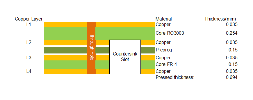
Countersink Slot L2-L4 (No Plating Required)
Slot depth: From Layer 2 to Layer 4
Plating: Not required
Purpose: For component mounting or connector integration
Surface finish: ENIG over exposed pads
Rogers RO3003™ – Product Introduction
RO3003™ is a ceramic-filled PTFE composite laminate offering a dielectric constant (Dk) of 3.00 ± 0.04 at 10GHz and an ultra-low dissipation factor (Df) of 0.0010. The material features a thermal coefficient of εr of -3 ppm/°C, ensuring stable electrical performance across a wide temperature range (-50°C to +150°C). With a thermal conductivity of 0.50 W/m/K and a decomposition temperature (Td) of 500°C, RO3003™ provides excellent thermal management for high-frequency applications.
The material exhibits outstanding dimensional stability with X/Y CTE of 17/16 ppm/°C and Z-axis CTE of 25 ppm/°C (-55°C to 288°C), closely matched to copper for reliable plated through holes. Its low moisture absorption (0.04%) ensures consistent electrical performance in humid environments.
Key Material Properties:
Dk: 3.00 ± 0.04 @ 10GHz (process)
Df: 0.0010 @ 10GHz/23°C
TCDK: -3 ppm/°C (-50°C to +150°C)
Thermal Conductivity: 0.50 W/m/K @ 50°C
CTE X/Y: 17/16 ppm/°C, CTE Z: 25 ppm/°C (-55°C to 288°C)
Td: 500°C
Moisture Absorption: 0.04%
Flammability: UL 94 V-0
Lead-Free Process Compatible
Features and Benefits Summary
| Feature | Benefit |
|---|---|
| Dk 3.00 ± 0.04 @ 10GHz | Stable dielectric constant for consistent impedance control |
| Df 0.0010 @ 10GHz | Ultra-low loss for high-frequency RF and microwave designs |
| TCDK: -3 ppm/°C | Excellent temperature stability, minimal variation |
| CTE: 17/16/25 ppm/°C | Excellent dimensional stability, reliable plated through holes |
| Td: 500°C | Exceptional thermal stability for demanding applications |
| Countersink Slot L2-L4 | Enables component mounting without plating |
| IPC-6012 Class 3 | High reliability for aerospace, defense, and automotive applications |
| ENIG finish | Excellent solderability, corrosion resistance, wire bondability |
RO3003™ Typical Properties (Data Sheet)
| Property | Typical Value | Units | Test Conditions | Test Method |
|---|---|---|---|---|
| Electrical Properties | ||||
| Dielectric Constant (process) | 3.00 ± 0.04 | — | 23°C, 10 GHz | — |
| Dielectric Constant (design) | 3.00 | — | 8 GHz - 40 GHz | — |
| Dissipation Factor | 0.0010 | — | 23°C, 10 GHz | — |
| Thermal Coefficient of Dielectric Constant | -3 | ppm/°C | -50 to 150°C, 10 GHz | — |
| Volume Resistivity | 10⁹ | MΩ-cm | Condition A | IPC TM-650 2.5.17.1 |
| Surface Resistivity | 10⁹ | MΩ | Condition A | IPC TM-650 2.5.17.1 |
| Thermal Properties | ||||
| Decomposition Temperature (Td) | 500 | °C | — | TGA-ASTM D3850 |
| Coefficient of Thermal Expansion - x | 17 | ppm/°C | -55 to 288°C, 23°C/50% RH | IPC TM-650 2.4.41 |
| Coefficient of Thermal Expansion - y | 16 | ppm/°C | -55 to 288°C, 23°C/50% RH | IPC TM-650 2.4.41 |
| Coefficient of Thermal Expansion - z | 25 | ppm/°C | -55 to 288°C, 23°C/50% RH | IPC TM-650 2.4.41 |
| Thermal Conductivity | 0.50 | W/(m.K) | 50°C | ASTM D5470 |
| Mechanical Properties | ||||
| Copper Peel Strength | 12.7 | lbs/in | 1 oz. EDC After Solder Float | IPC TM-650 2.4.8 |
| Young's Modulus | 930 / 823 | MPa | 23°C | ASTM D638 |
| Dimensional Stability (MD, CMD) | -0.06 / 0.07 | mm/m | Condition A | IPC TM-650 2.2.4 |
| Physical Properties | ||||
| Flammability | V-0 | — | — | UL 94 |
| Moisture Absorption | 0.04 | % | D48/50 | IPC TM-650 2.6.2.1 |
| Density | 2.1 | g/cm³ | 23°C | ASTM D792 |
| Specific Heat Capacity | 0.9 | J/g/K | — | Calculated |
| Lead Free Process Compatible | Yes | — | — | — |
Primary Application Areas
Automotive radar (up to 77 GHz)
Microwave, RF, and radar systems
Band pass filters
Microstrip patch antennas
Voltage-controlled oscillators (VCOs)
Phased array antennas
Satellite communications and base station antennas
Quality Assurance
Type of artwork supplied: Gerber RS-274-X
Accepted standard: IPC-6012 Class 3
Availability: Worldwide
100% Electrical test prior to shipment
ISO 9001:2015 & UL certified facility
Standard Thickness, Panel Sizes & Claddings
| Parameter | Options |
|---|---|
| Standard Thicknesses (RO3003) | 0.005" (0.13mm) ±0.0005", 0.010" (0.25mm) ±0.0007", 0.020" (0.51mm) ±0.0010", 0.030" (0.76mm) ±0.0015", 0.060" (1.52mm) ±0.0030" |
| Standard Panel Sizes | 12"x18" (305x457mm), 24"x18" (610x457mm) |
| Electrodeposited Copper Foil | ½ oz (18μm), 1 oz (35μm) |
| Rolled Copper Foil | ½ oz (18μm), 1 oz (35μm) |
Get a Quick Quote
Fill in the form below and our engineers will reply within 24 hours with technical specifications and pricing for 4-Layer Hybrid PCB with RO3003™ + FR4.
.jpg)