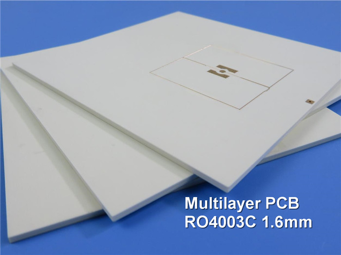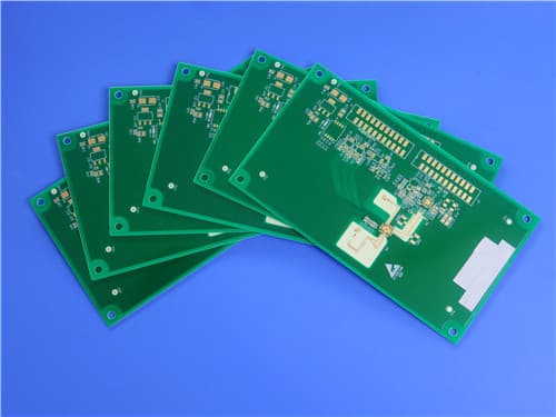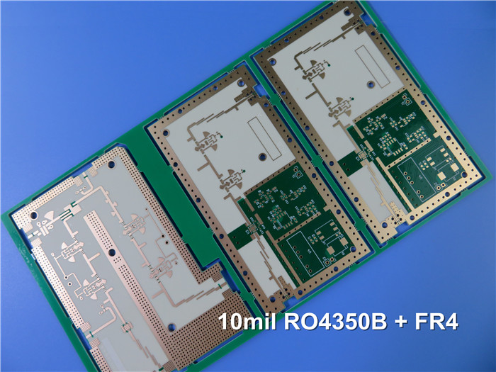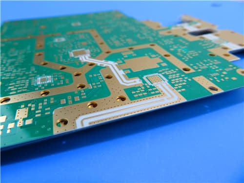
* PCBs are custom-made, picture & parameters for reference
6-Layer Hybrid PCB with RO4003C and FR4 for Impedance Controlled High Frequency Applications
(PCBs are custom-made; images and parameters are for reference only)
Introduction
This 6-layer hybrid high-frequency PCB features a Rogers RO4003C (20mil) core combined with FR4 Tg170℃ material, delivering excellent high-frequency performance with cost efficiency. RO4003C offers low dielectric loss and stable Dk (3.38±0.05), making it ideal for RF, microwave, broadband, and high-speed digital applications. The stack-up includes blind vias (L1-L2, L5-L6) and precise impedance control (L2:50Ω, L6:100Ω).
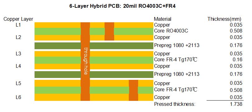

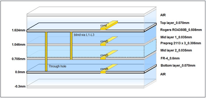
Stack-up Details
| Layer | Material | Thickness (mm) |
| L1 (Top Copper) | Copper 1oz | 0.035 |
| Core (RO4003C) | Rogers RO4003C 20mil | 0.508 |
| L2 (Inner Copper) | Copper 1oz | 0.035 |
| Prepreg 1080+2113 | FR4 Tg170℃ | 0.176 |
| L3 (Inner Copper) | Copper 1oz | 0.035 |
| Core FR4 | FR4 Tg170℃ | 0.016 |
| L4 (Inner Copper) | Copper 1oz | 0.035 |
| Prepreg 1080+2113 | FR4 Tg170℃ | 0.176 |
| L5 (Inner Copper) | Copper 1oz | 0.035 |
| Core FR4 | FR4 Tg170℃ | 0.016 |
| L6 (Bottom Copper) | Copper 1oz | 0.035 |
| Total Thickness (with copper) | ~1.738mm | |
Features and Benefits
1) RO4003C has one of the lowest temperature coefficients of dielectric constant, ideal for temperature-sensitive applications;
2) Stable Dk over a broad frequency range (Dk 3.38±0.05, Df 0.0027@10GHz);
3) Hybrid stack-up combines high-frequency performance with FR4 cost benefits;
4) Blind vias enable higher routing density and HDI designs;
5) Strict impedance control (coplane differential 50Ω/100Ω) ensures signal integrity;
6) ISO9001, ISO14001, IATF16949, UL certified facility;
7) Prototype to mass production capability.
Applications
RF/microwave circuits, matching networks, broadband communications, radar data acquisition, spread spectrum systems, duplexers, test & measurement equipment.
Parameter & Data Sheet
| PCB Size | 127mm x 103mm (including rails) |
| Board Type | Multilayer Hybrid PCB |
| Number of Layers | 6 layers |
| Surface Mount Components | Yes |
| Through Hole Components | Yes |
| Layer Stackup | Copper ----- L1 0.035mm (1oz) |
| RO4003C 0.508mm (20mil) | |
| Copper ----- L2 0.035mm (1oz) | |
| Prepreg 1080+2113 0.176mm | |
| Copper ----- L3 0.035mm (1oz) | |
| FR4 Tg170℃ 0.016mm | |
| Copper ----- L4 0.035mm (1oz) | |
| Prepreg 1080+2113 0.176mm | |
| Copper ----- L5 0.035mm (1oz) | |
| FR4 Tg170℃ 0.016mm | |
| Copper ----- L6 0.035mm (1oz) | |
| Technology | |
| Min Trace/Space | Per design requirements |
| Min/Max Hole Size | 0.3mm / 6.0mm |
| Hole Copper Thickness | 25μm (IPC-3) |
| Blind Vias | L1-L2, L5-L6 |
| Impedance Control | L2:50Ω±10% (coplane), L6:100Ω±10% (coplane) |
| Board Material | |
| High Frequency Material | RO4003C, Tg>280℃, Dk=3.38±0.05, Df=0.0027@10GHz |
| FR4 Material | FR4 Tg170℃, ITEQ or equivalent |
| Outer/Inner Copper | 1oz (35μm) finished on all layers |
| Final Board Thickness | 1.74mm ±10% |
| Plating & Coating | |
| Surface Finish | Hard Gold (Electroplated) |
| Solder Mask Color | Green (both sides) |
| Solder Mask Type | LPI, Taiyo PSR-2000GT600D |
| Legend | |
| Legend Side | Top and bottom |
| Legend Color | White, IJR-4000 MW300 |
| Testing | 100% Electrical Test (flying probe / continuity) |
| Artwork Format | Gerber RS-274-X, PCBDOC, etc. |
| Service Area | Worldwide |
RO4003C Material Introduction & Data Sheet Highlights
Rogers RO4000® series hydrocarbon ceramic laminates are designed for superior high frequency performance and low-cost circuit fabrication. RO4003C™ is a rigid, thermoset laminate that can be processed using standard FR-4 epoxy/glass processes, eliminating the need for specialized via preparation such as sodium etch. Key characteristics include:
- Dielectric Constant (Process Dk): 3.38 ± 0.05 @ 10 GHz (clamped stripline)
- Design Dk: 3.55 (average, 8–40 GHz differential phase length method)
- Dissipation Factor: 0.0027 @ 10 GHz / 0.0021 @ 2.5 GHz
- Thermal Coefficient of Dk: +40 ppm/°C (-50°C to 150°C)
- Tg: >280°C (TMA), Td: 425°C (TGA)
- CTE (X/Y/Z): 11 / 14 / 46 ppm/°C
- Moisture Absorption: 0.06% (48 hrs immersion, 50°C)
- Flammability: UL 94 V-0 (N/A for RO4003C per datasheet, but meets industry standards)
- Lead-Free Process Compatible: Yes
RO4003C laminates are offered in standard thicknesses including 0.008", 0.012", 0.016", 0.020", 0.032", and 0.060", with various panel sizes and electrodeposited copper foils (½ oz, 1 oz, etc.). The material's low Z-axis CTE ensures reliable plated through-hole quality even under severe thermal shock.
RO4003C Key Electrical Properties
| Property | Typical Value | Direction | Unit | Condition | Test Method |
| Dielectric Constant, εr (Process) | 3.38 ± 0.05 | Z | - | 10 GHz / 23°C | IPC-TM-650 2.5.5.5 Clamped Stripline |
| Dielectric Constant, εr (Design) | 3.55 | Z | - | 8 to 40 GHz | Differential Phase Length Method |
| Dissipation Factor, tan δ | 0.0027 | Z | - | 10 GHz / 23°C | IPC-TM-650 2.5.5.5 |
| Dissipation Factor, tan δ | 0.0021 | Z | - | 2.5 GHz / 23°C | IPC-TM-650 2.5.5.5 |
| Thermal Coefficient of εr | +40 | Z | ppm/°C | -50°C to 150°C | IPC-TM-650 2.5.5.5 |
| Volume Resistivity | 1.7 × 10¹⁰ | - | MΩ•cm | COND A | IPC-TM-650 2.5.17.1 |
| Surface Resistivity | 4.2 × 10⁹ | - | MΩ | COND A | IPC-TM-650 2.5.17.1 |
| Electrical Strength | 31.2 (780) | Z | KV/mm (V/mil) | 0.51mm (0.020") | IPC-TM-650 2.5.6.2 |
Mechanical & Thermal Properties
| Property | Typical Value | Direction | Unit | Condition | Test Method |
| Tensile Modulus | 19,650 (2,850) | X | MPa (ksi) | RT | ASTM D638 |
| Tensile Modulus | 19,450 (2,821) | Y | MPa (ksi) | RT | ASTM D638 |
| Tensile Strength | 139 (20.2) | X | MPa (ksi) | RT | ASTM D638 |
| Tensile Strength | 100 (14.5) | Y | MPa (ksi) | RT | ASTM D638 |
| Flexural Strength | 276 (40) | - | MPa (kpsi) | - | IPC-TM-650 2.4.4 |
| Dimensional Stability | <0.3 | X,Y | mm/m (mils/inch) | after etch +E2/150°C | IPC-TM-650 2.4.39A |
| CTE (X / Y / Z) | 11 / 14 / 46 | X/Y/Z | ppm/°C | -55 to 288°C | IPC-TM-650 2.4.41 |
| Tg | >280 | - | °C (TMA) | A | IPC-TM-650 2.4.24.3 |
| Td | 425 | - | °C (TGA) | - | ASTM D3850 |
| Thermal Conductivity | 0.71 | - | W/m/°K | 80°C | ASTM C518 |
| Moisture Absorption | 0.06 | - | % | 48 hrs immersion, 50°C | ASTM D570 |
| Density | 1.79 | - | g/cm³ | 23°C | ASTM D792 |
| Copper Peel Strength | 1.05 (6.0) | - | N/mm (pli) | after solder float, 1 oz. EDC Foil | IPC-TM-650 2.4.8 |
| Flammability | N/A | - | - | - | UL 94 |
| Lead-Free Process Compatible | Yes | - | - | - | - |
Standard Thicknesses
| Thickness | Tolerance |
| 0.008" (0.203mm) | ±0.0010" |
| 0.012" (0.305mm) | ±0.0010" |
| 0.016" (0.406mm) | ±0.0015" |
| 0.020" (0.508mm) | ±0.0015" |
| 0.032" (0.813mm) | ±0.0020" |
| 0.060" (1.524mm) | ±0.0040" |
Applications
RO4003C is widely used in RF/microwave circuits, matching networks, controlled impedance transmission lines, broadband systems, radar data acquisition, spread spectrum, duplexers, and high-speed digital designs. Its low loss and stable Dk over temperature and frequency make it an ideal substrate for demanding high-frequency applications.
Typical end-use products include:
- Microwave mixers and converters
- Radar and communication systems
- Test and measurement equipment
- Wireless infrastructure (5G, Wi-Fi)
- Automotive radar and sensors
Get a Quick Quote
Fill in the form below and our engineers will reply within 24 hours with technical specifications and pricing for 6-Layer Hybrid PCB with RO4003C + FR4.
.jpg)