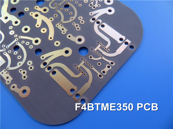
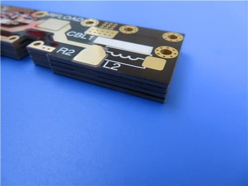
F4BTME320 High Frequency PCB 2oz Copper 1.0mm Thick With Immersion Gold
(PCB's are custom-made products, the picture and parameters shown are just for reference)
Brief Introduction
This is a 2-layer high-frequency printed circuit board (PCB) built on Wangling F4BTME320 substrates. Both the top and bottom layers feature 70 µm (2 oz) copper, starting from 1 oz plating. The design supports surface mount components on the top side, while through-hole components are not utilized.
The technology specifications include a minimum trace width of 4 mil and a minimum spacing of 6 mil, enabling precise circuit design. The surface finish is immersion gold, which enhances solderability and provides excellent corrosion resistance. Additionally, a black solder mask is applied to the top side of the PCB, offering durability and an appealing aesthetic while protecting the underlying circuitry from environmental factors.
PCB Specifications
F4BTME320 High Frequency PCB 2oz Copper 1.0mm Thick With Immersion Gold |
|
PCB SIZE |
70 x 70mm = 1PCS |
BOARD TYPE |
Double sided PCB |
Number of Layers |
2 layers |
Surface Mount Components |
YES |
Through Hole Components |
NO |
LAYER STACKUP |
copper ------- 70um(1 oz+plate) TOP layer |
F4BTME320 - 1.0mm |
|
copper ------- 70um(1 oz+plate) BOT Layer |
|
Minimum Trace and Space: |
4 mil / 6 mil |
Minimum / Maximum Holes: |
0.4 mm / 1.2 mm |
Number of Different Holes: |
7 |
Number of Drill Holes: |
92 |
Number of Milled Slots: |
2 |
Number of Internal Cutouts: |
1 |
Impedance Control: |
no |
BOARD MATERIAL |
|
Glass Epoxy: |
F4BTME320 Dk3.2 |
Final foil external: |
2 oz |
Final foil internal: |
N/A |
Final height of PCB: |
1.1 mm ±10% |
PLATING AND COATING |
|
Surface Finish |
Immersion Gold |
Solder Mask Apply To: |
Top, Black |
Solder Mask Color: |
Black |
CONTOUR/CUTTING |
Routing |
MARKING |
|
Side of Component Legend |
Top |
Colour of Component Legend |
White |
Manufacturer Name or Logo: |
Marked on the board in a conductor and leged FREE AREA |
VIA |
Plated through hole(PTH), minimum size 0.4mm. |
FLAMIBILITY RATING |
UL 94-V0 Approval MIN. |
DIMENSION TOLERANCE |
|
Outline dimension: |
0.0059" |
Board plating: |
0.0029" |
Drill tolerance: |
0.002" |
TEST |
100% Electrical Test prior shipment |
TYPE OF ARTWORK TO BE SUPPLIED |
email file, Gerber RS-274-X, PCBDOC etc |
SERVICE AREA |
Worldwide, Globally. |
.jpg)
F4BTME High-Frequency Laminates
F4BTME high-frequency laminates are composed of glass fiber cloth, nano-ceramic filling, and polytetrafluoroethylene resin, produced through scientific preparation and strict pressing processes. This series is based on the F4BM dielectric layer, enhanced with high-dielectric and low-loss nanoscale ceramics, resulting in:
Higher dielectric constant, Improved heat resistance, Lower coefficient of thermal expansion, Higher insulation resistance, Better thermal conductivity, Maintained low loss characteristics
F4BTME is cladded with reverse treated copper foil (RTF), offering an excellent PIM index, more accurate line control, and lower conductor loss, with optional thicknesses available in 0.5 oz and 1 oz.
Our PCB Capability (F4BTME)
| PCB Capability (F4BTME) | |||
|---|---|---|---|
| PCB Material: | PTFE / glass fiber cloth / Nano-ceramic filler | ||
| Designation (F4BTME) | F4BTME | DK (10GHz) | DF (10 GHz) |
| F4BTME298 | 2.98±0.06 | 0.0018 | |
| F4BTME300 | 3.0±0.06 | 0.0018 | |
| F4BTME320 | 3.2±0.06 | 0.0020 | |
| F4BTME350 | 3.5±0.07 | 0.0025 | |
| Layer count: | Single Sided, Double Sided PCB, Multilayer PCB, Hybrid PCB | ||
| Copper weight: | 0.5oz (17µm), 1oz (35µm), 2oz (70µm) | ||
| Dielectric thickness: | 0.25mm, 0.508mm, 0.762mm, 0.8mm, 1.0mm, 1.016mm, 1.27mm, 1.524mm, 2.0mm, 3.0mm, 4.0mm, 5.0mm, 6.0mm, 8.0mm, 10.0mm, 12.0mm | ||
| PCB size: | ≤400mm X 500mm | ||
| Solder mask: | Green, Black, Blue, Yellow, Red etc. | ||
| Surface finish: | Bare copper, HASL, ENIG, Immersion silver, Immersion tin, OSP, Pure gold, ENEPIG etc. | ||
Data Sheet (F4BTME)
| Product Technical Parameters & Product Models & Data Sheet | |||||||
|---|---|---|---|---|---|---|---|
| Property | Test Conditions | Unit | F4BTME298 | F4BTME300 | F4BTME320 | F4BTME350 | |
| Dielectric Constant (Typical) | 10GHz | / | 2.98 | 3.0 | 3.2 | 3.5 | |
| DK Tolerance | / | / | ±0.06 | ±0.06 | ±0.06 | ±0.07 | |
| Loss Tangent @10GHz | 10GHz | / | 0.0018 | 0.0018 | 0.0020 | 0.0025 | |
| Loss Tangent @20GHz | 20GHz | / | 0.0023 | 0.0023 | 0.0026 | 0.0035 | |
| Volume Resistivity | Standard | MΩ.cm | ≥1×10^7 | ||||
| Surface Resistivity | Standard | MΩ | ≥1×10^6 | ||||
| Thermal Conductivity | Z direction | W/(M.K) | 0.42 | 0.42 | 0.50 | 0.54 | |
| PIM (F4BTME only) | / | dBc | ≤-160 | ||||
| Flammability | / | UL-94 | V-0 | ||||
Get a Quick Quote
Fill in the form below and our engineers will reply within 24 hours with technical specifications and pricing for F4BTME320 High Frequency PCB (1.0mm DK3.2 2oz Copper).
.jpg)