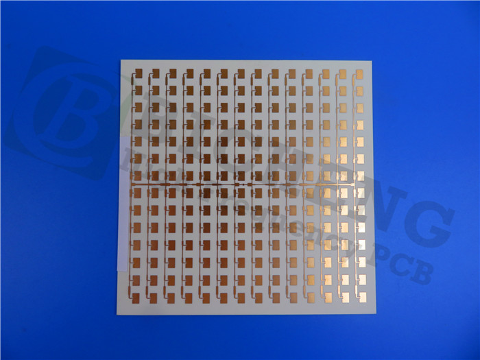
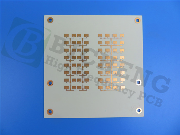
RO4003C LoPro PCB Rogers 12.7mil Reverse Treated Foil (RTF) Circuit Board for High Speed Back Planes
(Printed Circuit Boards are custom-made products; the images and specifications shown are for reference only.)
Product Description
RO4003C LoPro laminates utilize proprietary technology from Rogers that allows reverse treated foil to bond effectively with standard RO4003C dielectric. This innovation results in a laminate with low conductor loss, enhancing insertion loss and signal integrity while preserving all the desirable attributes of the standard RO4003C laminate system.
Features and Benefits
RO4003C materials are reinforced hydrocarbon/ceramic laminates featuring very low profile reverse treated foil, providing several advantages:
Lower Insertion Loss:Improved signal transmission efficiency.
Low Passive Intermodulation (PIM):Enhances overall performance in RF applications.
Increased Signal Integrity:Ensures clearer signal transmission.
High Circuit Density:Supports complex circuit designs without compromising performance.
Thermal and Design Characteristics
Low Z-axis Coefficient of Thermal Expansion:Facilitates multi-layer board capability and design flexibility.
Lead-Free Process Compatible:Supports high-temperature processing and meets environmental regulations.
CAF Resistant:Increases reliability in harsh environments.
Typical Applications
1.Digital applications such as servers, routers, and high-speed backplanes
2.Cellular base station antennas and power amplifiers
3.LNBs for direct broadcast satellites
4.RF Identification Tags
PCB Capability (RO4003C LoPro)
Our PCB Capability (RO4003C LoPro) |
|
PCB Material: |
Hydrocarbon Ceramic Laminates |
Designation: |
RO4003C LoPro |
Dielectric constant: |
3.38±0.05 |
Layer count: |
Double Layer, Multilayer, Hybrid PCB |
Copper weight: |
0.5oz (17 µm), 1oz (35µm), 2oz (70µm) |
PCB thickness: |
12.7mil (0.323mm), 16.7mil (0.424mm), 20.7mil(0.526mm), 32.7mil (0.831mm), 60.7mil(1.542mm) |
PCB size: |
≤400mm X 500mm |
Solder mask: |
Green, Black, Blue, Yellow, Red etc. |
Surface finish: |
Bare copper, HASL, ENIG, OSP, Immersion tin etc.. |
Typical Properties of RO4003C LoPro
RO4003C LoPro |
|||||
Property |
Typical Value |
Direction |
Units |
Condition |
Test Method |
Dielectric Constant, Process |
3.38 ± 0.05 |
z |
-- |
10 GHz/23°C |
IPC-TM-650 2.5.5.5 Clamped Stripline |
Dielectric Constant, Design |
3.5 |
z |
-- |
8 to 40 GHz |
Differential Phase Length Method |
Dissipation Factor tan, d |
0.0027 0.0021 |
z |
-- |
10 GHz/23°C 2.5 GHz/23°C |
IPC-TM-650 2.5.5.5 |
Thermal Coeffifi cient of er |
40 |
z |
ppm/°C |
-50°C to 150°C |
IPC-TM-650 2.5.5.5 |
Volume Resistivity |
1.7 X 10¹⁰ |
|
MΩ•cm |
COND A |
IPC-TM-650 2.5.17.1 |
Surface Resistivity |
4.2 X 10⁹ |
|
MΩ |
COND A |
IPC-TM-650 2.5.17.1 |
Electrical Strength |
31.2(780) |
z |
KV/mm(V/mil) |
0.51mm(0.020”) |
IPC-TM-650 2.5.6.2 |
Tensile Modulus |
26889(3900) |
Y |
MPa(kpsi) |
RT |
ASTM D638 |
Tensile Strength |
141(20.4) |
Y |
MPa(kpsi) |
RT |
ASTM D638 |
Flexural Strength |
276(40) |
|
MPa(kpsi) |
|
IPC-TM-650 2.4.4 |
Dimensional Stability |
<0.3 |
X,Y |
mm/m(mils/inch) |
after etch +E2/150°C |
IPC-TM-650 2.4.39A |
Coeffifi cient of Thermal Expansion |
11 |
x |
ppm/°C |
-55 to 288°C |
IPC-TM-650 2.1.41 |
14 |
y |
||||
46 |
z |
||||
Tg |
>280 |
|
°C TMA |
A |
IPC-TM-650 2.4.24.3 |
Td |
425 |
|
°C TGA |
|
ASTM D3850 |
Thermal Conductivity |
0.64 |
|
W/m/°K |
80°C |
ASTM C518 |
Moisture Absorption |
0.06 |
|
% |
48 hrs immersion 0.060” sample Temperature 50°C |
ASTM D570 |
Density |
1.79 |
|
gm/cm3 |
23°C |
ASTM D792 |
Copper Peel Strength |
1.05(6.0) |
|
N/mm(pli) |
after solder float 1 oz. TC Foil |
IPC-TM-650 2.4.8 |
Flammability |
N/A |
|
|
|
UL 94 |
Lead-Free Process Compatible |
Yes |
|
|
|
|