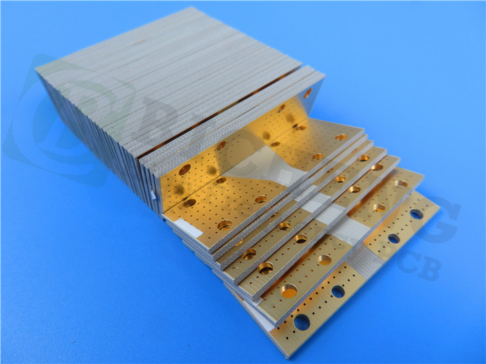
Rogers 6035 High Frequency PCB Built On Double Sided 20mil Core With Immersion Gold for Power Amplifiers
(Printed Circuit Boards are custom-made products, the picture and parameters shown are just for reference)
RT/duroid 6035HTC High-Frequency Circuit Materials by Rogers Corporation
RT/duroid 6035HTC is a ceramic-filled PTFE composite designed for high power RF and microwave applications. With a thermal conductivity nearly 2.4 times greater than standard RT/duroid 6000 products, and featuring copper foil (both electrodeposited and reverse treated) that offers exceptional long-term thermal stability, RT/duroid 6035HTC laminates are an outstanding choice for high power applications.
.jpg)
Features and Benefits
1.High Thermal Conductivity
Enhanced dielectric heat dissipation allows for lower operating temperatures in high power applications.
2.Low Loss Tangent
Delivers excellent performance at high frequencies.
3.Thermally Stable Low Profile and Reverse Treated Copper Foil
Results in lower insertion loss and superior thermal stability of traces.
4.Advanced Filler System
Provides improved drillability and extended tool life compared to circuit materials that contain alumina.
Typical Applications
1.High Power RF and Microwave Amplifiers
2.Power Amplifiers, Couplers, Filters
3.Combiners, Power Dividers
PCB Capability (RT/duroid 6035HTC)
PCB Capability (RT/duroid 6035HTC) |
|
PCB Material: |
Ceramic-filled PTFE composites |
Designation: |
RT/duroid 6035HTC |
Dielectric constant: |
3.50±0.05 |
Layer count: |
Double Layer, Multilayer, Hybrid PCB |
Copper weight: |
0.5oz (17 µm), 1oz (35µm), 2oz (70µm) |
PCB thickness: |
10mil (0.254mm), 20mil(0.508mm), 30mil (0.762mm), 60mil(1.524mm) |
PCB size: |
≤400mm X 500mm |
Solder mask: |
Green, Black, Blue, Yellow, Red etc. |
Surface finish: |
Bare copper, HASL, ENIG, OSP etc.. |
Data Sheet of RT/duroid 6035HTC
Property |
Typical Value RT/duroid 6035HTC |
Direction |
Unit |
Condition |
Test Method |
Dielectric Constant, εr Process |
3.50 ± 0.05 |
Z |
- |
10 GHz/23°C |
IPC-TM-650 2.5.5.5 Clamped Stripline |
Dielectric Constant, εr |
3.6 |
Z |
- |
8 GHz - 40 GHz |
Differential Phase Length Method |
Dissipation Factor, |
0.0013 |
Z |
- |
10 GHz/23°C |
IPC-TM-650, 2.5.5.5 |
Thermal Coefficient of εr |
-66 |
Z |
ppm/°C |
-50°C to 150°C |
mod IPC-TM-650, 2.5.5.5 |
Dielectric Strength |
835 |
- |
V/Mil |
15 mil thickness |
IPC-TM-650, 2.5.6.2 |
Breakdown Voltage |
12.59 |
- |
kV |
15 mil thickness |
IPC-TM-650, 2.5.6 |
Volume Resistivity |
108 |
- |
MΩ•cm |
COND A |
IPC-TM-650, 2.5.17.1 |
Surface Resistivity |
108 |
- |
MΩ |
COND A |
IPC-TM-650, 2.5.17.1 |
Tensile Modulus |
329 |
MD |
kpsi |
40 hrs @ 23°C/50RH |
ASTM D638 |
Dimensional Stability |
-0.11 |
CMD |
mm/m |
0.030” 1 oz EDC foil |
IPC-TM-650, 2.4.39A |
Coefficient of Thermal |
19 |
X |
ppm/°C |
23°C/50% RH |
IPC-TM-650 2.4.41 |
19 |
Y |
||||
39 |
Z |
||||
Thermal Conductivity |
1.44 |
- |
W/m/K |
80°C |
ASTM C518 |
Moisture Absorption |
0.06 |
- |
% |
D24/23 |
IPC-TM-650 2.6.2.1 ASTM D570 |
Density |
2.2 |
- |
gm/cm3 |
23°C |
ASTM D-792 |
Copper Peel Strength |
7.9 |
- |
pli |
20 sec.@ 288°C |
IPC-TM-650 2.4.8 |
Flammability |
V-0 |
- |
- |
- |
UL 94 |
Lead-Free Process |
YES |
|
|
|
|