Rogers RO4003C High Frequency PCB with 8mil, 12mil, 20mil, 32mil and 60mil Coating with Immersion Gold, Silver, tin and OSP
(Custom PCBs are tailored products; the images and specifications provided are for reference only.)
Hello everyone,
Today, we are excited to introduce the high-frequency PCB constructed with RO4003C laminates.
Overview of RO4003C
RO4003C is a woven glass cloth reinforced hydrocarbon resin laminate filled with ceramic from Rogers Corporation. It exhibits electrical properties comparable to PTFE while maintaining processability similar to epoxy resin-based materials.
Advantages of RO4003C Laminates
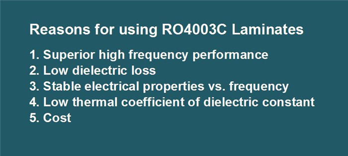
1. Superior High-Frequency Performance
RO4003C laminates are designed specifically for outstanding high-frequency performance, outperforming traditional PTFE materials.
2.Low Dielectric Loss
The low dielectric loss ensures excellent electrical performance, making it ideal for high-frequency applications.
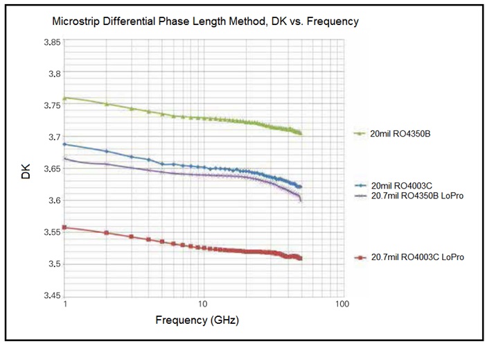
3. Stable Electrical Properties Across Frequencies
This material maintains stable properties for RF microwave circuits, matching networks, and controlled impedance transmission lines. Its dielectric constant remains consistent over a wide frequency range (Chart DK vs. frequency).
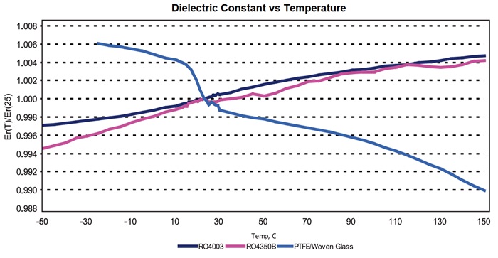
4. Low Thermal Coefficient of Dielectric Constant
RO4003C features one of the lowest temperature coefficients of dielectric constant, ensuring excellent dimensional stability(refer to Chart DK vs. Temperature). This is crucial for mixed dielectric multilayer PCB constructions and reliable plated through holes.
5. Cost-Effectiveness
RO4003C laminates can be manufactured using standard FR-4 processes without the need for specialized via preparation. They are compatible with automated handling systems and scrubbing equipment used for copper surface preparation. These attributes enable cost-effective production at scale, making them competitively priced.
PCB Specifications for RO4003C
PCB Material: |
Glass reinforced hydrocarbon ceramic laminates |
Code: |
RO4003C |
Dielectric constant: |
3.38 ±0.05 (process) |
3.55 (design) |
|
Layer count: |
1 Layer, 2 Layer, Multilayer, Hybrid type (Mixed) |
Copper weight: |
0.5oz (17 µm), 1oz (35µm), 2oz (70µm) |
PCB thickness: |
8mil (0.203mm), 12mil (0.305mm), 20mil (0.508mm) |
32mil (0.813mm), 60mil (1.524mm) |
|
PCB size: |
≤400mm X 500mm |
Solder mask: |
Green, Black, Blue, Yellow, Red etc. |
Surface finish: |
Bare copper, HASL, ENIG, Immersion tin, OSP,etc. |
Double-sided circuit boards made from RO4003C are available in various thicknesses, including 12mil, 16mil, 20mil, 32mil, and 60mil. These boards are suitable for both typical and unique microwave/radio frequency applications, such as base station antennas, power amplifiers, RFID technology, radar, and sensors.
The basic colour of RO4003C PCB is white.
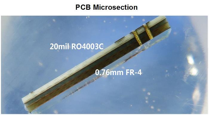
Multilayer and Hybrid PCBs
Multilayer PCB:
Multilayer circuit boards can be constructed using different cores of RO4003C. For instance, a 4-layer PCB may utilize 2 cores of 32mil RO4003C or a combination of 12mil and 20mil cores. The fixed thickness of the core is critical for the electrical length of RF lines on the PCB.
Hybrid PCB:
To reduce production costs while minimizing signal loss in high-frequency environments, hybrid PCBs combining FR-4 technology have become popular. This mature technology is widely adopted in the market now.This mature technology is widely adopted in the market now.
Our Services
We specialize in providing prototypes, small batch production, and mass manufacturing services. If you have any needs related to this type of PCB, please don't hesitate to reach out to us.
Thank you for your attention!
Appendix: Typical Values for RO4003C
RO4003C Typical Value |
|||||
Property |
RO4003C |
Direction |
Units |
Condition |
Test Method |
Dielectric Constant,εProcess |
3.38±0.05 |
Z |
|
10 GHz/23℃ |
IPC-TM-650 2.5.5.5 Clamped Stripline |
Dielectric Constant,εDesign |
3.55 |
Z |
|
8 to 40 GHz |
Differential Phase Length Method |
Dissipation Factortan,δ |
0.0027 |
Z |
|
10 GHz/23℃ |
IPC-TM-650 2.5.5.5 |
Thermal Coefficient of ε |
+40 |
Z |
ppm/℃ |
-50℃to 150℃ |
IPC-TM-650 2.5.5.5 |
Volume Resistivity |
1.7 x 10¹⁰ |
|
MΩ.cm |
COND A |
IPC-TM-650 2.5.17.1 |
Surface Resistivity |
4.2 x 10⁹ |
|
MΩ |
COND A |
IPC-TM-650 2.5.17.1 |
Electrical Strength |
31.2(780) |
Z |
Kv/mm(v/mil) |
0.51mm(0.020") |
IPC-TM-650 2.5.6.2 |
Tensile Modulus |
19,650(2,850) |
X |
MPa(ksi) |
RT |
ASTM D 638 |
Tensile Strength |
139(20.2) |
X |
MPa(ksi) |
RT |
ASTM D 638 |
Flexural Strength |
276 |
|
MPa |
|
IPC-TM-650 2.4.4 |
Dimensional Stability |
<0.3 |
X,Y |
mm/m |
after etch+E2/150℃ |
IPC-TM-650 2.4.39A |
Coefficient of Thermal Expansion |
11 |
X |
ppm/℃ |
-55℃to288℃ |
IPC-TM-650 2.4.41 |
Tg |
>280 |
|
℃ TMA |
A |
IPC-TM-650 2.4.24.3 |
Td |
425 |
|
℃ TGA |
|
ASTM D 3850 |
Thermal Conductivity |
0.71 |
|
W/M/oK |
80℃ |
ASTM C518 |
Moisture Absorption |
0.06 |
|
% |
48hrs immersion 0.060" |
ASTM D 570 |
Density |
1.79 |
|
gm/cm3 |
23℃ |
ASTM D 792 |
Copper Peel Stength |
1.05 |
|
N/mm |
after solder float 1 oz. |
IPC-TM-650 2.4.8 |
Flammability |
N/A |
|
|
|
UL 94 |
Lead-free Process Compatible |
Yes |
|
|
|
|