Rogers RO4835 High Frequency PCB - 10mil 20mil 30mil ED Copper 10.7mil 20.7mil 30.7mil LoPro Copper
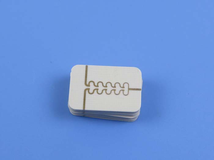
(Printed Circuit Boards are custom-made products, the picture and parameters shown are just for reference)
General Description
The Rogers RO4835 High Frequency PCB is a high-performance circuit board designed for applications requiring superior stability at elevated temperatures. Built on Rogers RO4835 substrates, this PCB features hydrocarbon ceramic laminates that offer excellent oxidation resistance, making it ideal for high-frequency and high-volume applications. RO4835 laminates provide nearly identical electrical and mechanical properties to the widely used RO4350B laminates, ensuring reliable performance. The material is compatible with both ED copper and LoPro copper, offering flexibility in design and manufacturing.
Features and Benefits
1.Improved Oxidation Resistance: Significantly more resistant to oxidation compared to typical thermoset microwave materials, ensuring long-term stability.
2.Low Loss Performance: Excellent electrical performance, ideal for high-frequency applications, especially in automotive radar and sensors.
3.Tight Dielectric Constant Tolerance: Ensures controlled impedance transmission lines for consistent signal integrity.
4.Lead-Free Process Compatibility: No blistering or delamination during lead-free soldering processes.
5.Low Z-Axis Expansion: Reliable plated through holes, ensuring robust mechanical connections.
6.Low In-Plane Expansion Coefficient: Stable performance across a wide range of processing temperatures.
7.CAF Resistant: Resistant to conductive anodic filamentation, enhancing long-term reliability.
Typical Applications
Automotive Radar and Sensors
Point-to-Point Microwave Systems
Power Amplifiers
Phased-Array Radar
RF Components
Our PCB Capability (RO4835)
| PCB Capability (RO4835) | |
| PCB Material: | Hydrocarbon Ceramic Laminates |
| Designation: | RO4835 |
| Dielectric constant: | 3.48 (10 GHz) |
| Dissipation Factor | 0.0037 (10 GHz) |
| Layer count: | Single Sided PCB, Double Sided PCB, Multilayer PCB, Hybrid PCB |
| Copper weight: | 1oz (35µm), 2oz (70µm) |
| Dielectric thickness (ED copper) | 6.6mil (0.168mm), 10mil (0.254mm), 20mil (0.508mm), 30mil (0.762mm), 60mil (1.524mm) |
| Dielectric thickness (LoPro copper) | 4mil (0.102mm), 7.3mil (0.186mm), 10.7mil (0.272mm), 20.7mil (0.526mm), 30.7mil (0.780mm), 60.7mil (1.542mm) |
| PCB size: | ≤400mm X 500mm |
| Solder mask: | Green, Black, Blue, Yellow, Red etc. |
| Surface finish: | Bare copper, HASL, Immersion gold, Immersion silver, Immersion tin, ENEPIG, OSP, Pure gold plated etc.. |
Appendix: Typical Values of RO4835
| Property | RO4835 | Direction | Units | Condition | Test Method |
| Dielectric Constant,εProcess | 3.48±0.05 | Z | - | 10 GHz/23℃ | IPC-TM-650 2.5.5.5 Clamped Stripline |
| Dielectric Constant,εDesign | 3.66 | Z | - | 8 to 40 GHz | Differential Phase Length Method |
| Dissipation Factortan,δ | 0.0037 | Z | - | 10 GHz/23℃ | IPC-TM-650 2.5.5.5 |
| Thermal Coefficient of ε | +50 | Z | ppm/℃ | -100℃to 150℃ | IPC-TM-650 2.5.5.5 |
| Volume Resistivity | 5 x 10⁸ | MΩ.cm | COND A | IPC-TM-650 2.5.17.1 | |
| Surface Resistivity | 7 x10⁸ | MΩ | COND A | IPC-TM-650 2.5.17.1 | |
| Electrical Strength | 30.2(755) | Z | Kv/mm(v/mil) | IPC-TM-650 2.5.6.2 | |
| Tensile Modulus | 7780(1128) | Y | MPa(ksi) | RT | ASTM D 638 |
| Tensile Strength | 136(19.7) | Y | MPa(ksi) | RT | ASTM D 638 |
| Flexural Strength | 186 (27) | Mpa (kpsi) | IPC-TM-650 2.4.4 | ||
| Dimensional Stability | <0.5 | X,Y | mm/m (mils/inch) |
after etch+E2/150℃ | IPC-TM-650 2.4.39A |
| Coefficient of Thermal Expansion | 10 12 31 |
X Y Z |
ppm/℃ | -55℃to288℃ | IPC-TM-650 2.4.41 |
| Tg | >280 | ℃ TMA | A | IPC-TM-650 2.4.24.3 | |
| Td | 390 | ℃ TGA | ASTM D 3850 | ||
| Thermal Conductivity | 0.66 | W/m/oK | 80℃ | ASTM C518 | |
| Moisture Absorption | 0.05 | % | 48hrs immersion 0.060" sample Temperature 50℃ |
ASTM D 570 | |
| Density | 1.92 | gm/cm3 | 23℃ | ASTM D 792 | |
| Copper Peel Stength | 0.88 (5.0) | N/mm (pli) | after solder float 1 oz. EDC Foil |
IPC-TM-650 2.4.8 | |
| Flammability | V-0 | UL 94 | |||
| Lead-free Process Compatible | Yes |