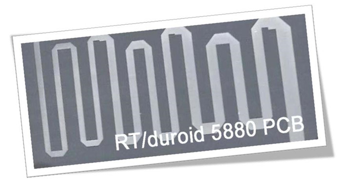
Rogers RT/Duroid 5880 RF PCB Coatings Available in 10mil, 20mil, 31mil, and 62mil
(Note: PCBs are custom-made products; the images and specifications provided are for reference only.)
Introduction to RT/Duroid 5880
Hello everyone,
Today, we are pleased to introduce our high-frequency PCBs constructed from RT/Duroid 5880 laminates. This advanced material from Rogers is a glass microfiber reinforced PTFE composite, specifically designed for demanding stripline and microstrip circuit applications.
Why Choose RT/Duroid 5880?
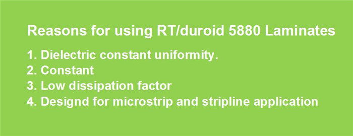
PCB Capabilities of RT/Duroid 5880
PCB Material: |
Glass microfiber reinforced PTFE composites |
Designation: |
RT/duroid 5880 |
Dielectric constant: |
2.2 ±0.02 (process) |
2.2 (design) |
|
Layer count: |
2 Layer, Multilayer, Hybrid type (Mixed) |
Copper weight: |
0.5oz (17 µm), 1oz (35µm), 2oz (70µm) |
PCB thickness: |
10mil (0.254mm), 20mil (0.508mm) |
31mil (0.787mm), 62mil (1.575mm) |
|
PCB size: |
≤400mm X 500mm |
Solder mask: |
Green, Black, Blue, Yellow, Red etc. |
Surface finish: |
Bare copper, HASL, ENIG, OSP, etc.. |
RT/Duroid 5880 can be fabricated into double-sided boards, multilayer boards, and hybrid types, available in thicknesses of 10mil, 20mil, 31mil, and 62mil.
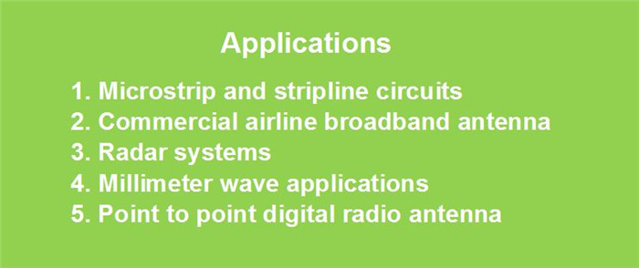
Typical Applications
The typical applications for RT/Duroid 5880 include:
Additional Properties
The standard color of RT/Duroid 5880 PCBs is black. This material also offers low water absorption and excellent chemical resistance, making it ideal for various environments.
If you have any questions or need further information, please feel free to contact us.
Thank you for reading!
Appendix: Typical Values of Rogers 5880
RT/duroid 5880 Typical Value |
||||||
Property |
RT/duroid 5880 |
Direction |
Units |
Condition |
Test Method |
|
Dielectric Constant,εProcess |
2.20 |
Z |
N/A |
C24/23/50 |
1 MHz IPC-TM-650 2.5.5.3 |
|
Dielectric Constant,εDesign |
2.2 |
Z |
N/A |
8GHz to 40 GHz |
Differential Phase Length Method |
|
Dissipation Factor,tanδ |
0.0004 |
Z |
N/A |
C24/23/50 |
1 MHz IPC-TM-650 2.5.5.3 |
|
Thermal Coefficient of ε |
-125 |
Z |
ppm/℃ |
-50℃to 150℃ |
IPC-TM-650 2.5.5.5 |
|
Volume Resistivity |
2 x 1077 |
Z |
Mohm cm |
C/96/35/90 |
ASTM D 257 |
|
Surface Resistivity |
3 x 10⁷ |
Z |
Mohm |
C/96/35/90 |
ASTM D 257 |
|
Specific Heat |
0.96(0.23) |
N/A |
j/g/k |
N/A |
Calculated |
|
Tensile Modulus |
Test at 23℃ |
Test at 100℃ |
N/A |
MPa(kpsi) |
A |
ASTM D 638 |
1070(156) |
450(65) |
X |
||||
860(125) |
380(55) |
Y |
||||
Ultimate Stress |
29(4.2) |
20(2.9) |
X |
|||
27(3.9) |
18(2.6) |
Y |
||||
Ultimate Strain |
6 |
7.2 |
X |
% |
||
4.9 |
5.8 |
Y |
||||
Compressive Modulus |
710(103) |
500(73) |
X |
MPa(kpsi) |
A |
ASTM D 695 |
710(103) |
500(73) |
Y |
||||
940(136) |
670(97) |
Z |
||||
Ultimate Stress |
27(3.9) |
22(3.2) |
X |
|||
29(5.3) |
21(3.1) |
Y |
||||
52(7.5) |
43(6.3) |
Z |
||||
Ultimate Strain |
8.5 |
8.4 |
X |
% |
||
7.7 |
7.8 |
Y |
||||
12.5 |
17.6 |
Z |
||||
Moisture Absorption |
0.02 |
N/A |
% |
0.62"(1.6mm) D48/50 |
ASTM D 570 |
|
Thermal Conductivity |
0.2 |
Z |
W/m/k |
80℃ |
ASTM C 518 |
|
Coefficient of Thermal Expansion |
31 |
X |
ppm/℃ |
0-100℃ |
IPC-TM-650 2.4.41 |
|
Td |
500 |
N/A |
℃ TGA |
N/A |
ASTM D 3850 |
|
Density |
2.2 |
N/A |
gm/cm3 |
N/A |
ASTM D 792 |
|
Copper Peel |
31.2(5.5) |
N/A |
Pli(N/mm) |
1oz(35mm)EDC foil |
IPC-TM-650 2.4.8 |
|
Flammability |
V-0 |
N/A |
N/A |
N/A |
UL 94 |
|
Lead-free Process Compatible |
Yes |
N/A |
N/A |
N/A |
N/A |
|