WL-CT High Frequency PCB: Advanced Performance for Modern Applications
(Note: Printed Circuit Boards are custom-made products. Images and parameters are for reference only.)
Introduction
The WL-CT series of high-frequency PCBs features organic polymer ceramic fiberglass cloth-covered copper boards, engineered with thermosetting resin. This innovative material combines hydrocarbon resin, ceramics, and fiberglass cloth to deliver exceptional low loss performance, meeting the demands of high-frequency designs. Leveraging fabrication techniques similar to FR4 materials, the WL-CT series simplifies processing compared to PTFE materials, ensuring enhanced stability and consistency in circuitry. This makes it an ideal substitute for comparable foreign products.
The unique blend of hydrocarbon resin and composite ceramics in the WL-CT series provides outstanding low loss, high-temperature resistance, and temperature stability. These materials maintain a stable temperature coefficient of dielectric constant and loss, possess a low thermal expansion coefficient, and feature a high glass transition (TG) value exceeding 280°C.
The WL-CT series offers a variety of dielectric constants: 3.00, 3.30, 3.38, 3.48, 4.10, and 6.15, catering to diverse application needs.
These materials can be paired with standard ED copper foil or reverse-treated RTF copper foil, the latter of which enhances Passive Intermodulation (PIM) performance while minimizing conductor and insertion loss. The RTF copper foil has an increased thickness of 0.018mm (0.7mil), ensuring superior adhesion.
Additionally, the WL-CT series can be combined with aluminum-based substrates to create high-frequency aluminum materials.
The circuit boards are compatible with standard FR4 fabrication techniques, and their excellent mechanical and physical properties allow for multiple lamination cycles. This makes them suitable for multi-layer, high-layer-count, and backplane processing, with superior capabilities in dense hole and fine line routing.
Product Features
1.Low dielectric constant tolerance with minimal loss.
2.Thermosetting resin-based system enhancing PCB processability and heat resistance.
3.Excellent temperature coefficient of dielectric constant, ensuring minimal temperature variation.
4.Thermal expansion coefficients in the X/Y directions equivalent to copper foil; low thermal expansion in the Z direction guarantees 5.dimensional stability and reliable copper connections in the holes.
6.High TG value above 280°C, maintaining dimensional integrity and copper quality even at elevated temperatures.
7.Superior thermal conductivity, outperforming thermoplastic materials of the same grade, ideal for high-power applications.
8.Commercially available, mass-produced, and cost-effective solutions.
9.Exceptional resistance to radiation, preserving stable dielectric and physical properties post-exposure.
10.Low outgassing performance, compliant with vacuum outgassing standards for aerospace applications.
Product Models & Data Sheet
| Product Technical Parameters | Product Models & Data Sheet | ||||||||
| Product Features | Test Conditions | Unit | WL-CT300 | WL-CT330 | WL-CT330Z | WL-CT338 | WL-CT350 | WL-CT440 | WL-CT615 |
| Dielectric Constant (Typical) | 10GHz | / | 3.00 | 3.30 | 3.30 | 3.38 | 3.48 | 4.10 | 6.15 |
| Dielectric Constant (Design) | 10GHz | / | 2.98 | 3.45 | 3.45 | 3.55 | 3.66 | 4.38 | 6.4 |
| Dielectric Constant Tolerance | / | / | ±0.05 | ±0.06 | ±0.06 | ±0.05 | ±0.05 | ±0.08 | ±0.15 |
| Loss Tangent (Typical) | 2GHz | / | 0.0025 | 0.0021 | 0.0025 | 0.0023 | 0.0030 | 0.0040 | 0.0032 |
| 10GHz | / | 0.0030 | 0.0026 | 0.0030 | 0.0029 | 0.0039 | 0.0050 | 0.0040 | |
| 20GHz | / | 0.0036 | 0.0033 | 0.0035 | 0.0038 | 0.0048 | / | / | |
| Dielectric Constant Temperature Coefficient | -55 º~150ºC | PPM/℃ | 27 | 43 | 43 | 45 | 52 | -21 | -122 |
| Peel Strength | 1 OZ RTF copper | N/mm | 0.85 | 1.0 | 0.85 | 1.0 | 0.85 | 1.0 | 0.9 |
| 1 OZ RTFcopper | N/mm | 0.72 | 0.72 | 0.72 | 0.72 | 0.72 | Not compatible | Not compatible | |
| Volume Resistivity | Standard Condition | MΩ.cm | 3×10⁸ | 5×10⁹ | 5×10⁹ | 6×10⁹ | 1×10⁹ | 1×10⁹ | 2×10⁷ |
| Surface Resistivity | Standard Condition | MΩ | 2×10⁸ | 5×10⁹ | 5×10⁹ | 7×10⁸ | 4×10⁹ | 5×10⁷ | 5×10⁶ |
| Electrical Strength (Z direction) | 5KW,500V/s | KV/mm | 28 | 22 | 22 | 31 | 31 | 27 | 30 |
| Breakdown Voltage (XY direction) | 5KW,500V/s | KV | 35 | 22 | 22 | 30 | 30 | 25 | 25 |
| Coefficientof Thermal Expansion (X, Y direction) | -55 º~288ºC | ppm/ºC | 15,14 | 15,13 | 15, 13 | 14, 16 | 11, 14 | 14, 18 | 15, 17 |
| Coefficientof Thermal Expansion (Z direction) | -55 º~288ºC | ppm/ºC | 31 | 39 | 39 | 50 | 34 | 35 | 33 |
| Thermal Stress | 288℃, 10s,3 times | / | No Delamination | No Delamination | No Delamination | No Delamination | No Delamination | No Delamination | No Delamination |
| Water Absorption | 20±2℃, 24 hours | % | 0.15 | 0.02 | 0.05 | 0.04 | 0.05 | 0.12 | 0.08 |
| Density | Room Temperature | g/cm3 | 1.57 | 1.82 | 1.78 | 1.78 | 1.90 | 2.00 | 2.18 |
| Long-Term Operating Temperature | High-Low Temperature Chamber | ℃ | -55~+260 | -55~+260 | -55~+260 | -55~+260 | -55~+260 | -55~+260 | -55~+260 |
| Thermal Conductivity | Z direction | W/(M.K) | 0.41 | 0.59 | 0.59 | 0.70 | 0.70 | 0.66 | 0.72 |
| PIM | Paired with RTF copper foil. | dBc | ≤-158 | ≤-157 | ≤-157 | ≤-158 | ≤-157 | N/A | N/A |
| Flammability | UL-94 | Grade | V-0 | Non-flame retardant | V-0 | Non-flame retardant | V-0 | V-0 | V-0 |
| TG | Standard | ℃ | >280℃ | >280℃ | >280℃ | >280℃ | >280℃ | >280℃ | >280℃ |
| TD | Initial Value | ℃ | 412 | 421 | 386 | 421 | 386 | 402 | 398 |
| Halogen | Yes | No | Yes | No | Yes | Yes | No | ||
| Material Composition | Hydrocarbon + Ceramic + Fiberglass cloth | ||||||||
Our PCB Capability (WL-CT)
| PCB Capability (WL-CT Series) | |||
| PCB Material: | Hydrocarbon resin, ceramic, and glass fiber cloth | ||
| Designation (WL-CT Series) | Designation | DK | DF |
| WL-CT300 | 3.0±0.05 | 0.0030 | |
| WL-CT330 | 3.3±0.06 | 0.0026 | |
| WL-CT330Z | 3.3±0.06 | 0.0030 | |
| WL-CT338 | 3.38±0.05 | 0.0029 | |
| WL-CT350 | 3.48±0.05 | 0.0039 | |
| WL-CT440 | 4.1±0.08 | 0.0050 | |
| WL-CT615 | 6.15±0.15 | 0.0040 | |
| Layer count: | Single Sided, Double Sided PCB, Multilayer PCB, Hybrid PCB | ||
| Copper weight: | 1oz (35µm), 2oz (70µm) | ||
| Dielectric thickness | ED Copper | TRF Copper | |
| 4mil | / | ||
| 8mil | 8.7mil | ||
| 12mil | / | ||
| 16mil | / | ||
| 20mil | 20.7mil | ||
| 28mil | / | ||
| 32mil | 32.7mil | ||
| 40mil | 40.7mil | ||
| 60mil | 60.7mil | ||
| 80mil | 80.7mil | ||
| PCB size: | ≤400mm X 500mm | ||
| Solder mask: | Green, Black, Blue, Yellow, Red etc. | ||
| Surface finish: | Bare copper, HASL, ENIG, Immersion silver, Immersion tin, OSP, Pure gold, ENEPIG etc.. | ||
WL-CT PCB and Applications
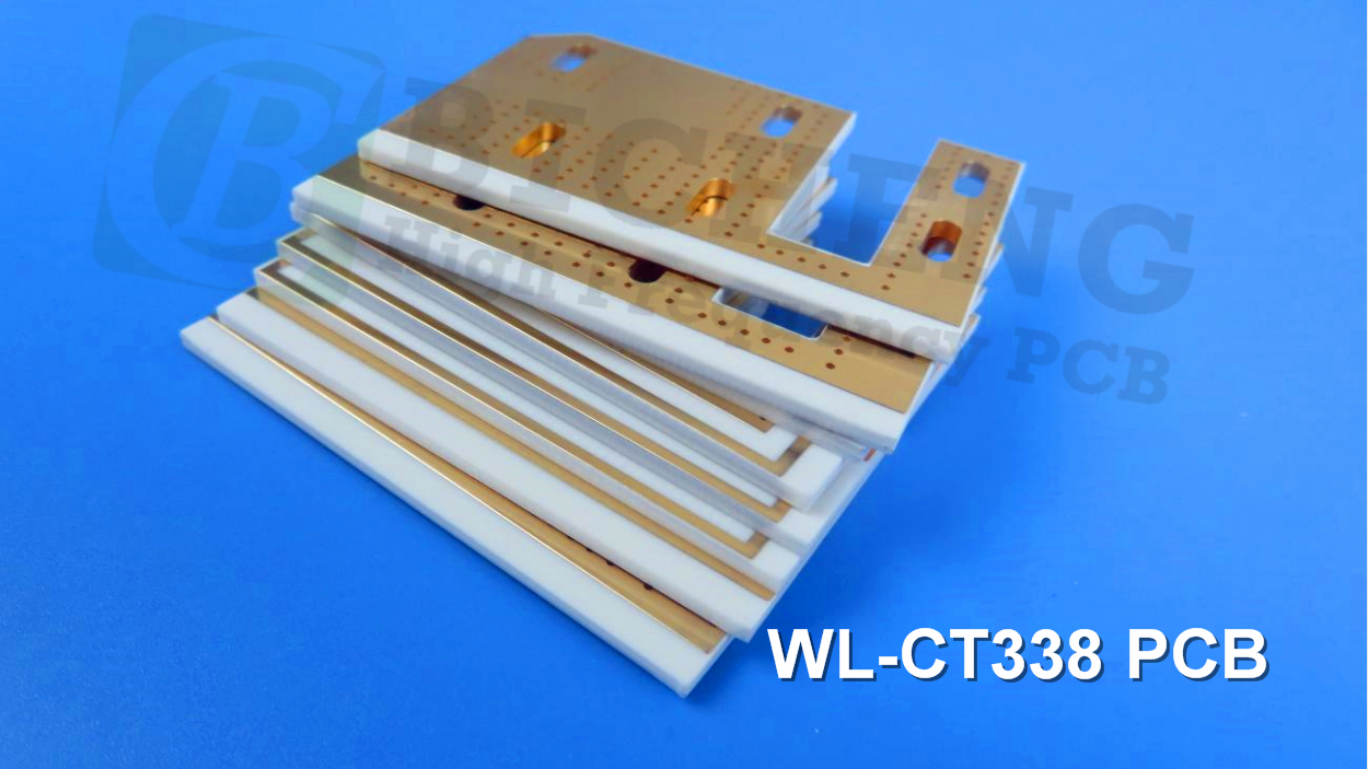
The WL-CT338 PCB, a double-sided 1.6mm board with immersion gold coating, is specifically designed for filters. These versatile WL-CT PCBs find applications in numerous sectors, including:
Base station and satellite antennas
Automotive radar, sensors, and navigation systems
Power amplifiers
Satellite high-frequency heads
RF devices and filters
WIMAX and distributed antennas
Compact patch antennas
Final Note on WL-CT Series Aluminum-Based Boards
This series includes aluminum-based substrates, where one side of the dielectric layer is covered with copper foil and the other with an aluminum layer for shielding or heat dissipation. Model numbers are formatted as WL-CT350-AL; for example, WL-CT350-AL indicates the WL-CT350 with an aluminum substrate.